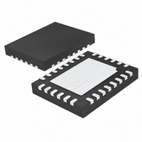
LT3743IUFD#PBF Linear Technology, LT3743IUFD#PBF Datasheet - Page 19

LT3743IUFD#PBF
Manufacturer Part Number
LT3743IUFD#PBF
Description
IC LED DRVR HP CONST CURR 28QFN
Manufacturer
Linear Technology
Type
High Power, Constant Currentr
Datasheet
1.LT3743EUFDPBF.pdf
(28 pages)
Specifications of LT3743IUFD#PBF
Topology
High Side, Low Side, PWM, Step-Down (Buck)
Number Of Outputs
1
Internal Driver
No
Type - Primary
General Purpose
Type - Secondary
RGB
Frequency
200kHz ~ 1MHz
Voltage - Supply
6 V ~ 36 V
Mounting Type
Surface Mount
Package / Case
28-QFN
Operating Temperature
-40°C ~ 125°C
Internal Switch(s)
Yes
Efficiency
92%
Led Driver Application
Lighting
No. Of Outputs
1
Output Current
20A
Output Voltage
40V
Input Voltage
6V To 36V
Dimming Control Type
PWM
Operating Temperature Range
-40°C To +125°C
Rohs Compliant
Yes
Lead Free Status / RoHS Status
Lead free / RoHS Compliant
Voltage - Output
-
Current - Output / Channel
-
Available stocks
Company
Part Number
Manufacturer
Quantity
Price
APPLICATIONS INFORMATION
Thermal Shutdown
The internal thermal shutdown within the LT3743 engages at
163°C and terminates switching, resets soft-start and shuts
down the PWMGL and PWMGH drivers. When the part has
cooled to 155°C, the internal reset is cleared and soft-start
is allowed to charge once the PWM signal is asserted.
Switching Frequency Synchronization
The nominal switching frequency of the LT3743 is determined
by the resistor from the RT pin to ground and may be set
from 200kHz to 1MHz. The internal oscillator may also be
synchronized to an external clock through the SYNC pin. The
external clock applied to the SYNC pin must have a logic low
below 0.3V and a logic high higher than 1.25V. The input fre-
quency must be 20% higher than the frequency determined
by the resistor at the RT pin. Input signals outside of these
specifi ed parameters will cause erratic switching behavior
and subharmonic oscillations. The synchronization range
is 240kHz to 1.2MHz. Synchronization is tested at 500kHz
with a 200k R
guaranteed by design. When synchronizing to an external
clock, please be aware that there will be a fi xed delay from the
input clock edge to the edge of switch. The SYNC pin must
be grounded if the synchronization to an external clock is not
required. When SYNC is grounded, the switching frequency
is determined by the resistor at the RT pin.
Shutdown and UVLO
The LT3743 has an internal UVLO that terminates switching,
resets all synchronous logic, and discharges the soft-start
capacitor for input voltages below 4.2V. The LT3743 also
has a precision shutdown at 1.55V on the EN/UVLO pin.
Partial shutdown occurs at 1.55V and full shutdown is
guaranteed below 0.5V with <1μA I
state. Below 1.5V, an internal current source provides 5.5μA
of pull-down current to allow for programmable UVLO
hysteresis. The following equations determine the voltage
divider resistors for programming the UVLO voltage and
hysteresis as confi gured in Figure 14.
R2 =
R1=
V
5.5μA
V
HYST
UVLO
1.55V •R2
T
resistor. Operation under other conditions is
– 1.55V
Q
in the full shutdown
The EN/UVLO pin as an absolute maximum voltage of
6V. To accommodate the largest range of applications,
there is an internal Zener diode that clamps this pin. For
applications where the supply range is greater than 4:1,
size R2 greater than 375k.
LED Current Derating Using the CTRL_T Pin
The LT3743 is designed specifi cally for driving high cur-
rent LEDs. Most high current LEDs require derating the
maximum current based on operating temperature to
prevent damage to the LED. In addition, many applications
have thermal limitations that will require the regulated
current to be reduced based on LED and/or board tem-
perature. To achieve this, the LT3743 uses the CTRL_T
pin to reduce the effective regulated current in the LED
for both the high and low control currents. While CTRL_H
and CTRL_L program the regulated current in the LED,
CTRL_T can be confi gured to reduce this regulated cur-
rent based on the analog voltage at the CTRL_T pin. The
LED/board temperature derating is programmed using a
resistor divider with a temperature dependant resistance
(Figure 15). When the board/LED temperature rises, the
CTRL_T voltage will decrease. To reduce the regulated
current, the CTRL_T voltage must be lower than voltage
at the CTRL_L and CTRL_H pins.
R2
R1
(OPTION A TO D)
Figure 15. LED Current Derating vs Temperature
Using NTC Resistor
V
CTRL_T
REF
LT3743
Figure 14. UVLO Confi guration
R
NTC
LT3743
EN/UVLO
A
V
R
IN
NTC
B
R2
R1
3743 F14
R
X
V
IN
R
NTC
C
LT3743
R
V
R
NTC
19
D
R
3743 F15
V
3743fb
R
X


