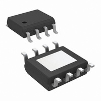
LM3402HVMR/NOPB National Semiconductor, LM3402HVMR/NOPB Datasheet - Page 11

LM3402HVMR/NOPB
Manufacturer Part Number
LM3402HVMR/NOPB
Description
IC LED DRVR HP CONST CURR 8-PSOP
Manufacturer
National Semiconductor
Series
PowerWise®r
Type
High Power, Constant Currentr
Specifications of LM3402HVMR/NOPB
Constant Current
Yes
Topology
PWM, Step-Down (Buck)
Number Of Outputs
1
Internal Driver
Yes
Type - Primary
Automotive
Type - Secondary
High Brightness LED (HBLED), White LED
Frequency
1MHz
Voltage - Supply
6 V ~ 75 V
Mounting Type
Surface Mount
Package / Case
8-PSOP
Operating Temperature
-40°C ~ 125°C
Current - Output / Channel
500mA
Internal Switch(s)
Yes
Efficiency
96%
Primary Input Voltage
75V
No. Of Outputs
1
Output Voltage
73V
Output Current
500mA
Voltage Regulator Case Style
PSOP
No. Of Pins
8
Operating Temperature Range
-40°C To +125°C
Svhc
No SVHC (15-Dec-2010)
Rohs Compliant
Yes
For Use With
551600000-001A/NOPB - BOARD WEBENCH SO8/SOP LM3404/2551600003-001A - BOARD WEBENCH MSOP LM3402LM3402HVEVAL - BOARD EVALUATION FOR LM3402HV
Lead Free Status / RoHS Status
Lead free / RoHS Compliant
Voltage - Output
-
Other names
LM3402HVMR
Available stocks
Company
Part Number
Manufacturer
Quantity
Price
Part Number:
LM3402HVMR/NOPB
Manufacturer:
NS/国半
Quantity:
20 000
The LM3402/02HV regulators should be operated in contin-
uous conduction mode (CCM), where inductor current stays
positive throughout the switching cycle. During steady-state
operationin the CCM, the converter maintains a constant
switching frequency, which can be selected using the follow-
ing equation:
AVERAGE LED CURRENT ACCURACY
The COT architecture regulates the valley of ΔV
portion of V
is also the average inductor current) the valley inductor cur-
rent is calculated using the following expression:
In this equation t
CS comparator, and is approximately 220 ns. The average
inductor/LED current is equal to I
ductor current ripple, Δi
Detailed information for the calculation of Δi
Design Considerations section.
MAXIMUM OUTPUT VOLTAGE
The 300 ns minimum off-time limits on the maximum duty cy-
cle of the converter, D
voltage V
V
F
= forward voltage of each LED, n = number of LEDs in
O(MAX)
SNS
. To determine the average LED current (which
is determined by the following equations:
SNS
I
F
represents the propagation delay of the
= I
MAX
L
L
:
= I
, and in turn ,the maximum output
series
L-MIN
L-MIN
+ Δi
L
plus one-half of the in-
/ 2
FIGURE 1. Comparator and One-Shot
L
is given in the
SNS
, the AC
11
The maximum number of LEDs, n
a single series string is governed by V
mum forward voltage of the LEDs used, V
expression:
At low switching frequency the maximum duty cycle and out-
put voltage are higher, allowing the LM3402/02HV to regulate
output voltages that are nearly equal to input voltage. The
following equation relates switching frequency to maximum
output voltage.
MINIMUM OUTPUT VOLTAGE
The minimum recommended on-time for the LM3402/02HV is
300 ns. This lower limit for t
cycle and output voltage that can be regulated based on input
voltage and switching frequency. The relationship is deter-
mined by the following equation:
20192105
ON
determines the minimum duty
MAX
, that can be placed in
O(MAX)
F(MAX)
and the maxi-
www.national.com
, using the


