ISL97801ARZ-TK Intersil, ISL97801ARZ-TK Datasheet

ISL97801ARZ-TK
Specifications of ISL97801ARZ-TK
Available stocks
Related parts for ISL97801ARZ-TK
ISL97801ARZ-TK Summary of contents
Page 1
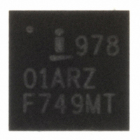
... NUMBER PART REEL/ (Note) MARKING QTY ISL97801ARZ 978 01ARZ - 20 Ld 4x4 QFN L20.4x4C ISL97801ARZ-TK 978 01ARZ 13” 4x4 QFN L20.4x4C 1,000 ISL97801ARZ-T 978 01ARZ 13” 4x4 QFN L20.4x4C 6,000 NOTE: Intersil Pb-free plus anneal products employ special Pb-free material sets; molding compounds/die attach materials and 100% matte tin plate termination finish, which are RoHS compliant and compatible with both SnPb and Pb-free soldering operations ...
Page 2
Absolute Maximum Ratings (T A Maximum pin voltage, all pins except below 6.5V V SWS1, SWS2, EN/PWM . . . . . . . . . . . . . . . . . . . . . . . ...
Page 3
Electrical Specifications BAT PARAMETER DESCRIPTION V Light Control Voltage Linear Input Range Mode = 1, analog control of LED current LEVEL FB Feedback Undervoltage Fault UV FAULT FB Feedback Overvoltage Fault OV FAULT f Switching Frequency SW ...
Page 4
Typical Performance Curves 100 8 LEDs I = 380mA 95 LEDpeak 99%@100Hz 90 50%@1kHz 85 80 50%@100Hz 99%@1kHz 75 10%@1kHz 70 50%@10kHz (V) IN FIGURE 1. 8 LEDs EFFICIENCY vs INPUT VOLTAGE vs ...
Page 5
Typical Performance Curves 10 5 LEDs 380mA LEDpeak 6 4 10% @ 100Hz 10% @ 10kHz -4 99% @ 10kHz -6 99% @ 100Hz -8 - (V) IN FIGURE ...
Page 6
Typical Performance Curves 41 5 LEDs I = 380mA 40 LEDpeak DUTY CYCLE = 10% 39 10% @ 100Hz 38 37 10% @ 10kHz (V) IN FIGURE 13. 5 LEDs LINE REGULATION ...
Page 7
Typical Performance Curves 8 LEDs V = 16V IN PWM = 100Hz FIGURE 19. 50% PWM DIMMING AT 100Hz 8 LEDs V = 12V IN PWM = 1kHz FIGURE 21. 10% PWM DIMMING AT 1kHz TRANSIENT RESPONSE WHEN LOAD DYNAMICALLY ...
Page 8
Typical Performance Curves FIGURE 25. OVP AND RESET Typical Boost Mode Application Diagram V BAT V DC 0.1µF TEMP SENSOR FIGURE 27. TYPICAL BOOST MODE APPLICATION CIRCUIT 8 ISL97801 (Continued) 8LEDs V I LED VIN VHI FAULT ...
Page 9
Pin Descriptions PIN NAME 1 VDC Internally regulated 5V supply, tracks V external supply if VIN is <5.5V. A minimum of 3.3µF decoupling capacitor is needed in this pin. 2 VHI Power FET gate drive supply. Can be biased with ...
Page 10
Functional Block Diagram 2.7V-16V GND START-UP V CHARGE PUMP START V DC POR REF EN O/P LIGHT CONTROL LEVEL MODE EN/PWM MODE CONTROL BUCK/ BOOSTN HALT VBAT FAULT VIN FAULT CONTROL HALT LDO AND REF AND TIMER V START CLK ...
Page 11
Theory of Operation General Description The ISL97801 is a flexible, highly integrated high-power LED driver consisting of a PWM switching controller and integrated 36V NDMOS power FET. The device can drive series high-power LED's at currents up ...
Page 12
PWM dimming, an internal timer delays system shutdown via EN/PWM for 50ms. FIGURE 31. OPERATION WITH ENL CONTROLLED FET FIGURE 32. OPERATION WITH NO ENL CONTROLLED FET Bias Current Dimming Current in the LED load ...
Page 13
VBAT 10µH VBAT FAULT L1 VIN ISL97801 SWD1 SWD2 ZOVP FB SWS1 SWS2 FIGURE 33. EXTERNAL OVP CIRCUIT Over Temperature Shutdown An internal sense circuit disables PWM switching if the die temperature exceeds +135°C. Switching is re-enabled when the temperature ...
Page 14
Rectifier Diode A high speed rectifier diode is necessary to prevent excessive voltage overshoot, especially in the boost configuration. Low forward voltage and reverse leakage current will minimize losses, making Schottky diodes the preferred choice. Similarly to the inductor, a ...
Page 15
TABLE 4. BOOST MODE COMPENSATION 12V OPERATION VFB I OUT 50mV 50mA Electrolytic 100mV 100mA Electrolytic 200mV 350mA Electrolytic 200mV 1A Electrolytic A Note about Ceramic Capacitors: Many ceramic capacitors have strong voltage and temperature coefficients which reduces effective capacitance ...
Page 16
Boost Mode Application Diagram V BAT Boost Mode with Over Current Fault and LED Temperature Protections Application Diagram V BAT TEMP SENSOR V FIGURE 36. BOOST MODE APPLICATION WITH OVER CURRENT FAULT PROTECTION AND LED TEMPERATURE PROTECTION 16 ISL97801 VIN ...
Page 17
... Accordingly, the reader is cautioned to verify that data sheets are current before placing orders. Information furnished by Intersil is believed to be accurate and reliable. However, no responsibility is assumed by Intersil or its subsidiaries for its use; nor for any infringements of patents or other rights of third parties which may result from its use ...
Page 18
Automotive Applications The LED load and ISL97801 may be protected against load dumps and other electrical faults in automotive supplies with a minor addition to the standard application schematic: • A reverse transient automotive-rated protection power schottky must be added ...
Page 19
Package Outline Drawing L20.4x4C 20 LEAD QUAD FLAT NO-LEAD PLASTIC PACKAGE Rev 0, 11/06 4.00 6 PIN 1 INDEX AREA 0.15 (4X) TOP VIEW ( 3. 8 TYP ) ( TYPICAL RECOMMENDED LAND PATTERN 19 ISL97801 16X ...


