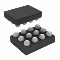
LM3530UME-40/NOPB National Semiconductor, LM3530UME-40/NOPB Datasheet - Page 29

LM3530UME-40/NOPB
Manufacturer Part Number
LM3530UME-40/NOPB
Description
IC LED DRVR PROGRAM I2C 12USMD
Manufacturer
National Semiconductor
Series
PowerWise®r
Datasheet
1.LM3530UME-40NOPB.pdf
(44 pages)
Specifications of LM3530UME-40/NOPB
Topology
PWM, Step-Up (Boost)
Number Of Outputs
1
Internal Driver
Yes
Type - Primary
Backlight
Type - Secondary
White LED
Frequency
500kHz
Voltage - Supply
2.7 V ~ 5.5 V
Mounting Type
Surface Mount
Package / Case
12-UFBGA
Operating Temperature
-40°C ~ 85°C
Current - Output / Channel
Adjustable
Led Driver Application
LED Backlighting, Portable Electronics
No. Of Outputs
1
Output Current
29.5mA
Output Voltage
40V
Input Voltage
2.7V To 5.5V
Rohs Compliant
Yes
Lead Free Status / RoHS Status
Lead free / RoHS Compliant
Voltage - Output
-
Other names
LM3530UME-40TR
BRIGHTNESS RAMP RATE REGISTER
The Brightness Ramp Rate Register controls the rate of rise
or fall of the LED current. Both the rising rate and falling rate
ALS ZONE INFORMATION REGISTER
The ALS Zone Information Register is a read-only register
that is updated every time the active ALS input(s) detect that
the ambient light has changed to a new zone as programmed
in the Zone Boundary Registers. See Zone Boundary Regis-
ters description. A new update to the ALS Zone Information
Bit 7
N/A
Bit 7
N/A
Bit 6
N/A
Bit 6
ALS Input
Select
00 = The Average of ALS1 and
ALS2 is used to control the LED
brightness
01 = ALS1 is used to control the
LED brightness
10 = ALS2 is used to control the
LED brightness
11 = The ALS input with the
highest voltage is used to
control the LED brightness
Bit 5
(BRRI2)
000 = 8 µs/step (1.106ms from 0 to Full Scale)
001 = 1.024 ms/step (130ms from 0 to Full Scale)
010 = 2.048 ms/step (260ms from 0 to Full Scale)
011 = 4.096 ms/step (520ms from 0 to Full Scale)
100 = 8.192 ms/step (1.04s from 0 to Full Scale)
101 = 16.384 ms/step (2.08s from 0 to Full Scale)
110 = 32.768 ms/step (4.16s from 0 to Full Scale)
111 = 65.538 ms/step (8.32s from 0 to Full Scale)
TABLE 7. Brightness Ramp Rate Register Description (0x30)
Bit 5
ALS Input
Select
TABLE 6. ALS Configuration Register Description (0x20)
Bit 4
(BRRI1)
FIGURE 20. Brightness Ramp Rate Register
FIGURE 21. ALS Zone Information Register
Bit 4
ALS Enable
00 or 10 = ALS is disabled. The
Brightness Register is used to
determine the LED current.
01 = ALS is enabled. The
Brightness Register is used to
determine the LED Current.
11 = ALS inputs are enabled.
Ambient light determines the
LED current.
Bit 3
(BRRI0)
29
Bit 3
ALS Enable
are independently adjustable
the bit settings.
Register is signaled by the INT output going from high to low.
A read-back of the ALS Zone Information Register will cause
the INT output to go open-drain again. The Zone Change Flag
(bit 3) is also updated on a Zone change and cleared on a
read back of the ALS Zone Information Register.
and
Bit 2
(BRRD2)
000 = 8 µs/step (1.106ms from Full Scale to 0)
001 = 1.024 ms/step (130ms from Full Scale to 0)
010 = 2.048 ms/step (260ms from Full Scale to 0)
011 = 4.096 ms/step (520ms from Full Scale to 0)
100 = 8.192 ms/step (1.04s from Full Scale to 0)
101 = 16.384 ms/step (2.08s from Full Scale to 0)
110 = 32.768 ms/step (4.16s from Full Scale to 0)
111 = 65.538 ms/step (8.32s from Full Scale to 0)
Table 8
detail the ALS Zone Information Register.
Bit 2
ALS
Averaging
Time
000 = 32 ms
001 = 64 ms
010 = 128 ms
011 = 256 ms
100 = 512 ms
101 = 1024 ms
110 = 2048 ms
111 = 4096 ms
Bit 1
(BRRD1)
Bit 1
ALS
Averaging
Time
Figure 20
30086612
30086611
and
Bit 0
(BRRD0)
Table 7
Bit 0
ALS
Averaging
Time
www.national.com
Figure 21
describe


