LM3530UME-40/NOPB National Semiconductor, LM3530UME-40/NOPB Datasheet - Page 19
LM3530UME-40/NOPB
Manufacturer Part Number
LM3530UME-40/NOPB
Description
IC LED DRVR PROGRAM I2C 12USMD
Manufacturer
National Semiconductor
Series
PowerWise®r
Datasheet
1.LM3530UME-40NOPB.pdf
(44 pages)
Specifications of LM3530UME-40/NOPB
Topology
PWM, Step-Up (Boost)
Number Of Outputs
1
Internal Driver
Yes
Type - Primary
Backlight
Type - Secondary
White LED
Frequency
500kHz
Voltage - Supply
2.7 V ~ 5.5 V
Mounting Type
Surface Mount
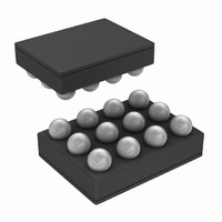
Package / Case
12-UFBGA
Operating Temperature
-40°C ~ 85°C
Current - Output / Channel
Adjustable
Led Driver Application
LED Backlighting, Portable Electronics
No. Of Outputs
1
Output Current
29.5mA
Output Voltage
40V
Input Voltage
2.7V To 5.5V
Rohs Compliant
Yes
Lead Free Status / RoHS Status
Lead free / RoHS Compliant
Voltage - Output
-
Other names
LM3530UME-40TR


EXPONENTIAL OR LINEAR BRIGHTNESS MAPPING
MODES
With bit [1] of the General Configuration Register set to 0 (de-
fault) exponential mapping is selected and the code in the
Brightness Control Register corresponds to the Full-Scale
LED current percentages in
[1] set to 1 linear mapping is selected and the code in the
Brightness Control Register corresponds to the Full-Scale
LED current percentages in
PWM INPUT POLARITY
Bit [6] of the General Configuration Register controls the
PWM input polarity. Setting this bit to 0 (default) selects pos-
itive polarity and makes the LED current (with PWM mode
enabled) a function of the positive duty cycle at PWM. With
this bit set to ‘0’ the LED current (with PWM mode enabled)
becomes a function of the negative duty cycle at PWM.
The PWM input is a logic level input with a frequency range
of 400Hz to 50kHz. Internal filtering of the PWM input signal
converts the duty cycle information to an average (analog)
control signal which directly controls the LED current.
Example: PWM + I
As an example, assume the the General Configuration Reg-
ister is loaded with (0x2D). From
LM3530 with:
Simple Enable OFF (bit 7 = 0)
Positive PWM Polarity (bit 6 = 0)
PWM Enabled (bit 5 = 1)
Full-Scale Current set at 15.5mA (bits [4:2] = 100)
Brightness Mapping set for Exponential (bit 1 = 0)
Device Enabled via I
Next, the Brightness Control Register is loaded with 0x73.
This sets the LED current to 51.406% of full scale (see ). Fi-
nally, the PWM input is driven with a 0 to 2V pulse waveform
at 70% duty cycle. The LED current under these conditions
will be:
Where BRT is the percentage of I
ness Control Register,
I
I
Device Enable bit (bit [0] of the General Configuration Regis-
2
2
C-COMPATIBLE CURRENT CONTROL ONLY
C-Compatible Control is enabled by writing a '1' to the I
2
C-Compatible Current Control
2
C (bit 0 = 1)
Table 2
Table 1
LED_FS
Table
and
and
as set in the Bright-
Figure
4, this sets up the
Figure
12.
11. With bit
2
C
19
ter), a '0' to the Simple Enable bit (bit 7), and a '0' to the PWM
Enable bit (bit 5). With bit 5 = 0, the duty cycle information at
the PWM input is not used in setting the LED current.
In this mode the LED current is a function of the Full-Scale
LED current bits (bits [4:2] of the General Configuration Reg-
ister) and the code in the Brightness Control Register. The
LED current mapping for the Brightness Control Register can
be linear or exponential depending on bit [1] in the General
Configuration Register (see Exponential or Linear Brightness
Mapping Modes section). Using I
the Full-Scale LED Current bits and the Brightness Control
Register code provides nearly 1016 possible current levels
selectable over the I
Example: I
As an example, assume the General Configuration Register
is loaded with 0x15. From this sets up the LM3530 with:
Simple Enable OFF (bit 7 = 0)
Positive PWM Polarity (bit 6 = 0)
PWM Disabled (bit 5 = 0)
Full-Scale Current set at 22.5mA (bits [4:2] = 101)
Brightness Mapping set for Exponential (bit 1 = 0)
Device Enabled via I2C (bit 0 = 1)
The Brightness Control Register is then loaded with 0x72
(48.438% of full-scale current from ). The LED current with
this configuration becomes:
Where BRT is the % of I
Register.
Next, the brightness mapping is set to linear mapping mode
(bit [1] in General Configuration Register set to 1). Using the
same Full-Scale current settings and Brightness Control Reg-
ister settings as before, the LED current becomes:
Which is higher now since the code in the Brightness Control
Register (0x72) corresponds to 89.76% of Full-Scale LED
Current due to the different mapping mode given in .
2
C-Compatible Current Control Only
2
C-compatible interface.
LED_FS
as set in the Brightness Control
2
C-Compatible Control Only,
www.national.com
Related parts for LM3530UME-40/NOPB
Image
Part Number
Description
Manufacturer
Datasheet
Request
R

Part Number:
Description:
IC LED DRVR PRGRAM I2C 10LED SMD
Manufacturer:
National Semiconductor
Datasheet:

Part Number:
Description:
10LED SERIES BACKLIGHT DRIVER
Manufacturer:
National Semiconductor
Part Number:
Description:
LM3530 PRODUCT BRIEF High Efficiency White LED Driver with Programmable Ambient Light Sensing Capability and I<sup>2</sup>C Compatible Interface; Package: MICRO SMD; No of Pins: 12; Qty per Container: 250/Reel
Manufacturer:
National Semiconductor
Part Number:
Description:
National Semiconductor [8-Bit D/A Converter]
Manufacturer:
National Semiconductor
Datasheet:
Part Number:
Description:
National Semiconductor [Media Coprocessor]
Manufacturer:
National Semiconductor
Datasheet:
Part Number:
Description:
Digitally Controlled Tone and Volume Circuit with Stereo Audio Power Amplifier, Microphone Preamp Stage and National 3D Sound
Manufacturer:
National Semiconductor
Datasheet:
Part Number:
Description:
Digitally Controlled Tone and Volume Circuit with Stereo Audio Power Amplifier, Microphone Preamp Stage and National 3D Sound
Manufacturer:
National Semiconductor
Datasheet:
Part Number:
Description:
AC97 Rev 2 Codec with Sample Rate Conversion and National 3D Sound
Manufacturer:
National Semiconductor
Part Number:
Description:
Manufacturer:
National Semiconductor
Datasheet:
Part Number:
Description:
Manufacturer:
National Semiconductor
Datasheet:
Part Number:
Description:
General Purpose, Low Voltage, Low Power, Rail-to-Rail Output Operational Amplifiers
Manufacturer:
National Semiconductor
Datasheet:
Part Number:
Description:
8-bit 20 MSPS flash A/D converter.
Manufacturer:
National Semiconductor
Datasheet:
Part Number:
Description:
Low Noise Quad Operational Amplifier
Manufacturer:
National Semiconductor
Datasheet:
Part Number:
Description:
Quad Differential Line Receivers
Manufacturer:
National Semiconductor
Datasheet: