ISL97631IHTZ-T7 Intersil, ISL97631IHTZ-T7 Datasheet
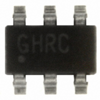
IC LED DRIVR WHITE BCKLGT TSOT-6

ISL97631IHTZ-T7

Manufacturer Part Number
ISL97631IHTZ-T7
Description
IC LED DRIVR WHITE BCKLGT TSOT-6
Manufacturer
Intersil
Type
Backlight, White LEDr
Datasheet

Specifications of ISL97631IHTZ-T7

Topology
PWM, Step-Up (Boost)
Number Of Outputs
1
Internal Driver
Yes
Type - Primary
Backlight
Type - Secondary
White LED
Frequency
800kHz ~ 1.8MHz
Voltage - Supply
2.7 V ~ 5.5 V
Voltage - Output
27V
Mounting Type
Surface Mount
Package / Case
TSOT-23-6, TSOT-6
Operating Temperature
-40°C ~ 85°C
Current - Output / Channel
30mA
Internal Switch(s)
Yes
Efficiency
85%
Lead Free Status / RoHS Status
Lead free / RoHS Compliant
Other names
ISL97631IHTZ-T7

Available stocks

Company
Part Number
Manufacturer
Quantity
Price
Part Number:
ISL97631IHTZ-T7
Manufacturer:
INTERSIL
Quantity:
225
Part Number:
ISL97631IHTZ-T7
Manufacturer:
INTERSIL
Quantity:
20 000
Part Number:
ISL97631IHTZ-T7A
Manufacturer:
Intersil
Quantity:
500
Part Number:
ISL97631IHTZ-T7A
Manufacturer:
INTERSIL
Quantity:
20 000
White LED Boost Regulator With
Integrated Schottky Diode
The ISL97631 represents a high efficiency, constant
frequency PWM regulator with integrated boost diode and
FET. Designed for use in white LED driving applications, the
ISL97631 features efficiencies up to 85%. It operates at
1.35MHz switching frequency and operates from an input
voltage of between 2.7V and 5.5V. The maximum output
voltage of 27V enables the ISL97631 to drive up to 6 LEDs in
series. It is also possible to use the ISL97631 to drive LEDs
in series/parallel combination for applications requiring up to
15 LEDs.
Available in the 6 Ld TSOT package, the ISL97631 offers
high efficiency, constant frequency operation. It is specified
for operation over the -40°C to +85°C ambient temperature
range.
Pinout
Ordering Information
NOTE: Intersil Pb-free plus anneal products employ special Pb-free material sets; molding compounds/die attach materials and 100% matte tin plate
termination finish, which are RoHS compliant and compatible with both SnPb and Pb-free soldering operations. Intersil Pb-free products are MSL
classified at Pb-free peak reflow temperatures that meet or exceed the Pb-free requirements of IPC/JEDEC J STD-020.
ISL97631IHTZ-T7 (See Note)
ISL97631IHTZ-T7A (See Note)
PART NUMBER
VOUT
GND
LX
1
2
3
(6 LD TSOT)
TOP VIEW
ISL97631
®
1
631Z
631Z
Data Sheet
MARKING
6
5 FB
4
PART
VIN
ENAB
1-888-INTERSIL or 1-888-468-3774
3,000
PCS.
270
CAUTION: These devices are sensitive to electrostatic discharge; follow proper IC Handling Procedures.
Features
• Up to 6 LEDs in series
• 27V maximum output
• 2.7V to 5.5V input
• Up to 85% efficient
• 1.35MHz constant frequency
• Enable/PWM dimming control
• Pb-free plus anneal available (RoHS compliant)
Applications
• LED backlighting
• Cell phones
• PDAs
• Handheld games
• MP3 players
• GPS
• Other handheld devices
TAPE &
REEL
December 21, 2005
7”
7”
All other trademarks mentioned are the property of their respective owners.
|
6 Ld TSOT (Pb-free)
6 Ld TSOT (Pb-free)
Intersil (and design) is a registered trademark of Intersil Americas Inc.
(TAPE AND REEL)
Copyright Intersil Americas Inc. 2005. All Rights Reserved
PACKAGE
ISL97631
PKG. DWG. #
MDP0049
MDP0049
FN7370.1

Related parts for ISL97631IHTZ-T7

ISL97631IHTZ-T7 Summary of contents

Page 1

... MARKING ISL97631IHTZ-T7 (See Note) 631Z ISL97631IHTZ-T7A (See Note) 631Z NOTE: Intersil Pb-free plus anneal products employ special Pb-free material sets; molding compounds/die attach materials and 100% matte tin plate termination finish, which are RoHS compliant and compatible with both SnPb and Pb-free soldering operations. Intersil Pb-free products are MSL classified at Pb-free peak reflow temperatures that meet or exceed the Pb-free requirements of IPC/JEDEC J STD-020 ...

Page 2

Absolute Maximum Ratings (T A Input Voltage ( -0.3V to ...

Page 3

Typical Application L1 22µ 2.7V~5.5V OUT C1 ISL97631 1µF FB ENAB OFF/ON GND FIGURE 1. TYPICAL APPLICATION CIRCUIT Typical Performance Curves 700 600 500 400 300 200 100 (V) IN ...

Page 4

Block Diagram 1.35MHz 1.2MHz Oscillator and Ramp 1.2MHz Oscillator and Ramp Pin Descriptions PIN PIN NUMBER NAME DESCRIPTION 1 VOUT Output Pin. Connect to the anode of the top LED and the output filter capacitor . 2 GND Ground Pin. ...

Page 5

The magnitude of the PWM signal should be higher than the minimum ENAB voltage high. The bench PWM dimming test results are shown in Figure 8. In the test, two PWM frequencies 400Hz and 1kHz are chosen to compare the ...

Page 6

L1 22µ 2.7V~5.5V OUT C1 ISL97631 Dz 1µ ENAB OFF/ON R GND 4.75 FIGURE 10. LED DRIVER WITH OVERVOLTAGE PROTECTION CIRCUIT Components Selection The input capacitance is typically 0.22µF. The output capacitor ...

Page 7

PCB Layout Considerations The layout is very important for the converter to function properly. R must be located as close as possible to the FB SET and GND pins. Longer traces to the LEDs are OK. Similarly, the supply decoupling ...

Page 8

... Accordingly, the reader is cautioned to verify that data sheets are current before placing orders. Information furnished by Intersil is believed to be accurate and reliable. However, no responsibility is assumed by Intersil or its subsidiaries for its use; nor for any infringements of patents or other rights of third parties which may result from its use ...

Related keywords