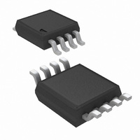
LM3401MM/NOPB National Semiconductor, LM3401MM/NOPB Datasheet - Page 8

LM3401MM/NOPB
Manufacturer Part Number
LM3401MM/NOPB
Description
IC LED DRIVER HIGH BRIGHT 8-MSOP
Manufacturer
National Semiconductor
Series
PowerWise®r
Type
HBLED Driverr
Datasheet
1.LM3401MMNOPB.pdf
(18 pages)
Specifications of LM3401MM/NOPB
Constant Current
Yes
Topology
PWM, Step-Down (Buck)
Number Of Outputs
1
Internal Driver
No
Type - Primary
General Purpose
Type - Secondary
High Brightness LED (HBLED)
Frequency
1.5MHz
Voltage - Supply
4.5 V ~ 35 V
Mounting Type
Surface Mount
Package / Case
8-MSOP, Micro8™, 8-uMAX, 8-uSOP,
Operating Temperature
-40°C ~ 125°C
Current - Output / Channel
1A
Internal Switch(s)
Yes
Efficiency
92%
Operating Supply Voltage (typ)
5/9/12/15/18/24V
Number Of Segments
1
Operating Temperature (min)
-40C
Operating Temperature (max)
125C
Operating Temperature Classification
Automotive
Package Type
MSOP
Pin Count
8
Mounting
Surface Mount
Power Dissipation
660mW
Operating Supply Voltage (min)
4.5V
Operating Supply Voltage (max)
35V
For Use With
LM3401EVAL - BOARD EVALUATION FOR LM3401
Lead Free Status / RoHS Status
Lead free / RoHS Compliant
Voltage - Output
-
Lead Free Status / Rohs Status
Compliant
Other names
LM3401MMTR
Available stocks
Company
Part Number
Manufacturer
Quantity
Price
Part Number:
LM3401MM/NOPB
Manufacturer:
NS/国半
Quantity:
20 000
www.national.com
Maximum switching frequency will typically occur around the
input voltage which corresponds to 25% duty cycle.
If the input voltage falls below the forward voltage of the LED
string, the LM3401 will operate at 100% duty cycle. In this
state, the anode voltage will be equal to the input voltage and
LED current is determined by the v-i curve of the LED. At
100% duty cycle, LED current will be continuous with a max-
imum value equal to the I
In some applications, maximum operating frequency will be
limited by the minimum on-time as shown in the following
equation:
When the on-time reaches minimum (150 ns typical) due to
increasing input voltage, the frequency will be reduced in or-
der to maintain the proper duty cycle.
INDUCTOR SELECTION
The most important parameters for the inductor are the in-
ductance and the current rating. The LM3401 operates over
a wide frequency range and can use a wide range of induc-
tance values.
Once an inductance value is determined from the frequency
equation, the maximum operating current must be verified.
Although peak-to-peak ripple current is controlled by the hys-
teresis value, there is some variation due to propagation
delay. This means that the inductance has a direct effect on
LED current line regulation.
In general, a larger inductor will result in lower frequency and
better line regulation. The actual peak-to-peak inductor cur-
rent can be calculated as follows:
Use the maximum value of Vin to determine the worst case
I
peak current, I
section.
Since the LM3401 can operate at 100% duty cycle, the in-
ductor must be rated to handle I
LED_RIP
value. This value should be used to determine the
FIGURE 4. Frequency vs Input Voltage
LED_PK
, shown in the Output Current Setting
LED_PK
LED_PK
level set at the HYS pin.
continuously.
30021425
8
RIPPLE REDUCTION CAPACITOR
The typical application schematic shown on the front page is
the simplest application of the LM3401. In this schematic, in-
ductor current is equal to LED current. Therefore, the equa-
tions for ripple current apply to both LED ripple and inductor
ripple.
However, LED ripple current can be reduced without altering
the inductor current by using a bypass capacitor placed in
parallel with the LED string (shown as C2 in the Figure 11
schematic).
This allows larger hysteresis values to be used while signifi-
cantly reducing ripple current in the LED string. Figure 5 below
shows this effect: inductor ripple current is unaffected while
LED ripple current is dramatically reduced.
If a ripple reduction capacitor is used, the equation for
SNS
LED average DC current and peak inductor current are not
affected by the ripple reduction capacitor. However, LED
peak current is reduced and switching frequency may shift
slightly.
Any type of capacitor can be used, provided the working volt-
age rating is sufficient. In general, higher capacitance and
lower ESR will provide more ripple reduction; a typical value
greater than 100 nF is recommended. Smaller capacitance
values will be less effective, and large ESR values may ac-
tually increase LED ripple current.
Despite its effectiveness to smooth LED ripple current, there
are two notable disadvantages to using a ripple reduction ca-
pacitor.
First, when used, care must be taken to avoid shorting the
LED anode to ground. If this occurs, the capacitor will force a
large negative voltage spike at the SNS pin which could dam-
age the IC.
Second, this capacitor will limit the maximum PWM dimming
frequency because it takes some additional time to charge
and discharge. Additionally, ceramic capacitors can generate
audible noise due to fast voltage changes during dimming. To
reduce audible noise, use the smallest possible case size,
use dimming frequencies below 500 Hz, or use a non-ceramic
ripple reduction capacitor.
A small bypass capacitor, in the range of 100 pF to 200 pF
can also be used to reduce high frequency switching noise.
This is recommended in higher current applications, where
FIGURE 5. LED Ripple Current Reduction with a 1 µF
HYS_MAX
only applies for 100% duty operation.
Ripple Reduction Capacitor
30021428


