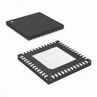
ISL6113IRZA Intersil, ISL6113IRZA Datasheet - Page 14

ISL6113IRZA
Manufacturer Part Number
ISL6113IRZA
Description
IC HOT PLUG CTRLR PCI-E 48-QFN
Manufacturer
Intersil
Type
Hot-Swap Controllerr
Datasheet
1.ISL6113IRZA.pdf
(24 pages)
Specifications of ISL6113IRZA
Applications
General Purpose, PCI Express
Internal Switch(s)
No
Voltage - Supply
3.3V, 12V
Operating Temperature
-40°C ~ 85°C
Mounting Type
Surface Mount
Package / Case
48-VFQFN Exposed Pad
Lead Free Status / RoHS Status
Lead free / RoHS Compliant
The VAUX outputs have a different circuit-breaker function.
The VAUX circuit breakers do not incorporate a fast-trip
detector, instead they regulate the current into a fault to
avoid exceeding their operating current limit. The circuit
breaker will trip due to an overcurrent on VAUX when the
programmable CR duration timer, t
the t
prematurely due to brief current transients. See Figures 16
and 17 for illustrations of the VAUX protection performance
into an over current (OC) and more severe OC condition
respectively. The ISL6113, ISL6114 AUX current control
responds proportionally to the severity of the OC condition
resulting in appropriately fast VAUX pull down and current
regulation until t
FLT
12IOUT
3 IOUT
12V
FIGURE 14. ISL6113 12VMAIN WOC SHUTDOWN
FIGURE 15. ISL6113 3VMAIN WOC SHUTDOWN
timer prevents the circuit breaker from tripping
OUT
3VGATE
FILTER
has expired.
14
FLT
expires. This use of
CFILTER
CFILTER
3V
OUT
12VGATE
ISL6113, ISL6114
In the fault latch mode set by leaving L/R pin open, following a
fault condition, the outputs can be turned on again via the ON
inputs (if the fault occurred on one of the MAIN outputs), via
the AUXEN inputs (if the fault occurred on the AUX outputs),
or by cycling both ON and AUXEN (if faults occurred on both
the MAIN and AUX outputs). When the circuit breaker trips,
FAULT will be asserted. In the fault retry mode, set by
grounding the L/R pin the ISL6113, ISL6114 will initiate an
automatic restart about every 1.5s until successful.
The ISL6113, ISL6114 current regulation duration (t
is set by external capacitors at the CFILTER pins to GND.
Once the CR mode is entered, the external cap is charged
with a 2.5µA current source to 1.25V. Once this threshold
has been reached the IC then turns-off all fault the related
FETs and sets the FAULT output low. For a desired t
the value for C
C
FIGURE 17. VAUX WOC REGULATION AND SHUTDOWN
FILTER
CFILTER
VAUX
FIGURE 16. VAUX OC REGULATION AND SHUTDOWN
IAUX
VAUX
IAUX
=
nominal t
------------------------------------------- -
CFILTER
500kΩ
FILTER
is given by Equation 4:
September 25, 2007
CFILTER
FILTER
FILTER
FN6457.0
(EQ. 4)
)
,


