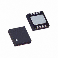
LTC4300A-3CDD Linear Technology, LTC4300A-3CDD Datasheet - Page 9

LTC4300A-3CDD
Manufacturer Part Number
LTC4300A-3CDD
Description
IC BUFFER BUS HOTSWAP 2WR 8DFN
Manufacturer
Linear Technology
Type
Hot-Swap Switchr
Datasheet
1.LTC4300A-3CMS8.pdf
(12 pages)
Specifications of LTC4300A-3CDD
Applications
General Purpose, Buffer/Bus Extender
Internal Switch(s)
Yes
Voltage - Supply
2.7 V ~ 5.5 V
Operating Temperature
0°C ~ 70°C
Mounting Type
Surface Mount
Package / Case
8-WFDFN Exposed Pad
Lead Free Status / RoHS Status
Contains lead / RoHS non-compliant
Available stocks
Company
Part Number
Manufacturer
Quantity
Price
Company:
Part Number:
LTC4300A-3CDD
Manufacturer:
LT
Quantity:
10 000
APPLICATIO S I FOR ATIO
Resistor Pull-Up Value Selection
The system pull-up resistors must be strong enough to
provide a positive slew rate of 1.25V/µs on the SDA and
SCL pins, in order to activate the boost pull-up currents
during rising edges. Choose maximum resistor value R
using the formula:
where R is the pull-up resistor value in ohms, V
the minimum V
capacitance in picofarads (pF).
In addition, regardless of the bus capacitance, always
choose R ≤ 16k for V
V
high voltages on SDAOUT and SCLOUT to connect the
backplane to the card, and these pull-up values are needed
to overcome the precharge voltage.
CC
R ≤ (V
ENA1
ENA2
V
SDA
SCL
V
= 3.6V maximum. The start-up circuitry requires logic
CC2
CC
10k
R7
CC(MIN)
BACKPLANE
10k
R8
CC
– 0.6)(800,000)/C
Figure 3. The LTC4300A-3 in a PCI Application Where All the Pins Have the Same Length.
ENABLE Should be Held Low Until All Transients Associated with the Live Insertion Have Settled
U
voltage and C is the equivalent bus
CC
CONNECTOR
BACKPLANE
= 5.5V maximum, R ≤ 24k for
U
W
U
CC(MIN)
is
C2 0.01µF
C4 0.01µF
Live Insertion and Capacitance Buffering Application
Figures 3 and 4 illustrate the usage of the LTC4300A-3 in
applications that take advantage of both its Hot Swap con-
trolling and capacitance buffering features. In all of these
applications, note that if the I/O cards were plugged di-
rectly into the backplane, all of the backplane and card ca-
pacitances would add directly together, making rise- and
fall-time requirements difficult to meet. Placing a
LTC4300A-3 on the edge of each card, however, isolates
the card capacitance from the backplane. For a given I/O
card, the LTC4300A-3 drives the capacitance of everything
on the card and the backplane must drive only the capaci-
tance of the LTC4300A-3, which is less than 10pF.
V
SDAIN
SCLIN
V
SDAIN
SCLIN
CC
CC
I/O PERIPHERAL CARD 1
I/O PERIPHERAL CARD 2
LTC4300A-3
LTC4300A-3
V
V
GND
GND
CC2
CC2
C1
0.01µF
C3
0.01µF
SDAOUT
SDAOUT
SCLOUT
SCLOUT
ENABLE
ENABLE
LTC4300A-3
R1
10k
R4
10k
R2
10k
R3
10k
R5
10k
R6
10k
sn4300a3 4300a3fs
CARD_SDA
CARD_SCL
CARD2_SDA
CARD2_SCL
4300A-3 F03
9


