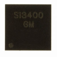
SI3400-E1-GM Silicon Laboratories Inc, SI3400-E1-GM Datasheet - Page 7

SI3400-E1-GM
Manufacturer Part Number
SI3400-E1-GM
Description
IC POWER OVER ETHERNET 20QFN
Manufacturer
Silicon Laboratories Inc
Type
Power over Ethernet Switch (PoE)r
Datasheet
1.SI3400-E1-GM.pdf
(20 pages)
Specifications of SI3400-E1-GM
Package / Case
20-QFN
Applications
IP Phones, Power over LAN, Network Routers and Switches
Internal Switch(s)
Yes
Current Limit
525mA
Voltage - Supply
2.8 V ~ 57 V
Operating Temperature
-40°C ~ 85°C
Mounting Type
Surface Mount
Maximum Operating Temperature
+ 85 C
Minimum Operating Temperature
- 40 C
Mounting Style
SMD/SMT
Lead Free Status / RoHS Status
Lead free / RoHS Compliant
For Use With
336-1326 - KIT REF DESIGN PWR OVER ETHERNET
Lead Free Status / Rohs Status
Lead free / RoHS Compliant
Other names
336-1385
SI3400-E-GM
SI3400-E-GM
Table 4. Electrical Characteristics (Continued)
Table 5. Total Power Dissipation
Table 6. Package Thermal Characteristics
Power Dissipation
Power Dissipation*
*Note: Silicon Laboratories recommends the on-chip diode bridges be bypassed when output power requirements are >10 W
Thermal resistance
(junction to ambient)
VDD accuracy @ 0.8 mA
Softstart charging current
Thermal Shutdown
Thermal Shutdown Hysteresis
Notes:
1. Transient surge defined in IEC60060 as a 1000 V impulse of either polarity applied to CT1–CT2 or SP1–SP2. The
2. The classification currents are guaranteed only when recommended RCLASS resistors are used, as specified in
3. IPORT includes full operating current of switching regulator controller.
4. The PD interface includes dual-level input current limit. At turn-on, before the HSO load capacitor is charged, the
5. See “AN296: Using the Si3400/01 PoE PD Controller in Isolated and Non-Isolated Designs” for more information.
6. Applies to non-isolated applications only (VOUT on schematic in Figure 1).
Description
(Si3401) or in thermally-constrained applications. For more information, see “AN313: Using the Si3400 and Si3401 in
High Power Applications”.
shape of the impulse shall have a 300 ns full rise time and a 50 µs half fall time with 201 Ω source impedance.
Table 10.
current limit is set at the inrush level. After the capacitor has been charged within ~1.25 V of VNEG, the operating
current limit is engaged. This higher current limit remains active until the UVLO lower limit has been tripped or until the
hotswap switch is sufficiently current-limited to cause a foldback of the HSO voltage.
Parameter
Parameter
VPORT = 50 V, V
VPORT = 50 V, V
bridges bypassed
Symbol
θ
JA
Condition
OUT
OUT
36 V < VPORT < 57 V
Junction temperature
= 5 V, 2 A
= 5 V, 2 A w/ diode
Still air; assumes a minimum of
nine thermal vias are connected
to a 2 in
the package “pad” node
(VNEG).
Description
Rev. 0.9
2
Test Condition
heat spreader plane for
Min
—
—
Min
4.5
—
—
—
Si3400/Si3401
Typ
1.2
0.7
Typ
Typ
160
44
12
—
—
Max
—
—
Max
5.5
25
—
—
Units
°C/W
Units
W
W
Unit
µA
ºC
ºC
V
7


