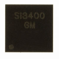
SI3400-E1-GM Silicon Laboratories Inc, SI3400-E1-GM Datasheet - Page 10

SI3400-E1-GM
Manufacturer Part Number
SI3400-E1-GM
Description
IC POWER OVER ETHERNET 20QFN
Manufacturer
Silicon Laboratories Inc
Type
Power over Ethernet Switch (PoE)r
Datasheet
1.SI3400-E1-GM.pdf
(20 pages)
Specifications of SI3400-E1-GM
Package / Case
20-QFN
Applications
IP Phones, Power over LAN, Network Routers and Switches
Internal Switch(s)
Yes
Current Limit
525mA
Voltage - Supply
2.8 V ~ 57 V
Operating Temperature
-40°C ~ 85°C
Mounting Type
Surface Mount
Maximum Operating Temperature
+ 85 C
Minimum Operating Temperature
- 40 C
Mounting Style
SMD/SMT
Lead Free Status / RoHS Status
Lead free / RoHS Compliant
For Use With
336-1326 - KIT REF DESIGN PWR OVER ETHERNET
Lead Free Status / Rohs Status
Lead free / RoHS Compliant
Other names
336-1385
SI3400-E-GM
SI3400-E-GM
Si3400/Si3401
3. Functional Description
The Si3400 and Si3401 consist of two major functions:
a hotswap controller/interface and a complete pulse-
width-modulated switching regulator (controller and
power FET).
3.1. Overview
The hotswap interfaces of the Si3400 and Si3401
provide the complete front end of an 802.3-compliant
PD. The Si3400 and Si3401 also include two full diode
bridges, a transient voltage surge suppressor, detection
circuit, classification current source, and dual-level
hotswap current limiting switch. This high level of
integration enables direct connection to the RJ-45
connector, simplifies system design, and provides
significant advantages for reliability and protection. The
Si3400 and Si3401 require only four standard external
components (detection resistor, optional classification
resistor, load capacitor, and input capacitor) to create a
fully 802.3-compliant interface. For more information
about
“AN313: Using the Si3400 and Si3401 in High Power
Applications” and “AN314: Power Combining Circuit for
PoE for up to 18.5 W Output”.
The Si3400 and Si3401 integrate a complete pulse-
width modulated switching regulator that includes the
controller and power FET. The switching regulator
utilizes a constant frequency pulse-width modulated
controller optimized for all possible load conditions in
PoE applications. The regulator integrates a low on-
resistance (Ron) switching power MOSFET that
minimizes power dissipation, increases overall regulator
efficiency, and simplifies system design. An integrated
error amplifier, precision reference, and programmable
soft-start current source provide the flexibility of using a
non-isolated buck regulator topology or an isolated
flyback regulator topology.
10
CT2/SP2
CT1/SP1
supporting
VNEG
POWER LOSS
AND PROTECTION
DIODE BRIDGES
DETECTOR
higher-power
PLOSS
VPOSF
applications,
Figure 3. Hotswap Block Diagram
VPOSS
12V
22V
0V
12V
OFF
ON
CLASSIFICATION
OFF
ON
DETECTION
CONTROL
CONTROL
see
Rev. 0.9
RDET
RCL
The Si3400 and Si3401 are designed to operate with
both 802.3-compliant Power Sourcing Equipment (PSE)
and pre-standard (legacy) PSEs that do not adhere to
the 802.3 specified inrush current limits. The Si3400
and Si3401 are compatible with compliant and legacy
PSEs because they use two levels for the hotswap
current limits. By setting the initial inrush current limit to
a low level, a PD based on the Si3400 or Si3401
minimizes the current drawn from either a compliant or
legacy PSE during startup. After powering up, the
Si3400 and Si3401 automatically switch to a higher-
level current limit, thereby allowing the PD to consume
up to 12.95 W (the max power allowed by the 802.3
specification).
The inrush current limit specified by the 802.3 standard
can generate high transient power dissipation in the PD.
By properly sizing the devices and implementing on-
chip thermal protection, the Si3400 and Si3401 can go
through multiple turn-on sequences without overheating
the package or damaging the device. The switching
regulator power MOSFET has been conservatively
designed and sized to withstand the high peak currents
created when converting a high-voltage, low-current
supply
Excessive power cycling or short circuit faults will
engage the thermal overload protection to prevent the
onboard power MOSFETs from exceeding their safe
and reliable operating ranges.
3.2. PD Hotswap Controller
The Si3400 and Si3401 hotswap controllers change
their mode of operation based on the input voltage
applied to the CT1 and CT2 pins or the SP1 and SP2
pins, the 802.3-defined modes of operation, and internal
controller requirements. Table 9 defines the modes of
operation for the hotswap interface.
CURRENT
LIMIT
CENTRAL BIAS
HI/LO
BANDGAP REF
into
HOTSWAP
CONTROL
a
low-voltage,
OFF
ON
1.32V
10V
5V
32V
39V
ISOSSFT
STARTUP & BIAS
SWITCHER
high-current
SSFT
VREF
IABS
ITC
HSO
supply.


