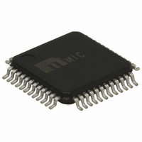
MIC2591B-2YTQ Micrel Inc, MIC2591B-2YTQ Datasheet - Page 21

MIC2591B-2YTQ
Manufacturer Part Number
MIC2591B-2YTQ
Description
IC CTRLR HOTPLUG PCI DUAL 48TQFP
Manufacturer
Micrel Inc
Type
Hot-Swap Controllerr
Datasheet
1.MIC2591B-2YTQ.pdf
(34 pages)
Specifications of MIC2591B-2YTQ
Applications
General Purpose, PCI Express
Internal Switch(s)
No
Voltage - Supply
3.3V, 12V
Operating Temperature
0°C ~ 70°C
Mounting Type
Surface Mount
Package / Case
48-TQFP
Lead Free Status / RoHS Status
Lead free / RoHS Compliant
Other names
576-1098
Available stocks
Company
Part Number
Manufacturer
Quantity
Price
Part Number:
MIC2591B-2YTQ
Manufacturer:
MICREL
Quantity:
20 000
of the fault conditions listed above and deasserted when
one or all STAT[A/B] Register Bits D[4], D[2], D[0] and/or CS
Register Bits D[2], D[1] are reset upon the execution of an
SMBus “echo reset” WRITE_BYTE cycle. For polled-mode
operation, the INTMSK bit should be set to Logical “1,” thereby
inhibiting /INT output pin operation.
For those SMI-control applications where the /FORCE_ON[A/B]
inputs are needed for diagnostic purposes, the /FORCE_ON[A/B]
inputs must be enabled; that is, CNTRL[A/B] Register Bit
D[2] should read Logical “0.” Once /FORCE_ON[A/B] inputs
are asserted, all output voltages are present with all circuit
protection features disabled, including overtemperature pro-
tection on VAUX[A/B] outputs. To inhibit /FORCE_ON[A/B]
operation, a Logical “1” shall be written to the CNTRL[A/B]
Register Bit D[2] location(s).
HPI-only Control Applications
In applications where the MIC2591B is controlled only by the
HPI, SMBus signals SCL, SDA, and /INT signals are con-
nected to V
the MIC2591B’s /FAULT[A/B] outputs are activated after
power-on-reset and become asserted when:
Either or both external ON[A/B] and AUXEN[A/B] input signals
March 2005
STBY
STBY
STBY
VAUX_OUT[A/B]
/PWRGD_[A/B]
/FAULT_[A/B]
12VOUT[A/B]
as shown in Figure 6. In this confi guration,
as shown in Figure 6. In this confi guration,
AUXEN[A/B]
3VOUT[A/B]
I
AUX_OUT[A/B]
VSTBY
I
ON[A/B]
3VOUT[A/B]
/INT*
0
0
0
0
0
0
0
0
0
0
0
I
I
I
I
STEADY-STATE
STEADY-STATE
LIM(3V)
LIM(AUX)
UVLO
t POR
+3.3V
Figure 9. Hot-Plug Interface Operation
V
IH
t FLT
V
IL
21
*
* /INT de-asserted by software
are asserted, AND
In order to clear /FAULT[A/B] outputs once asserted, either
or both ON[A/B] and AUXEN[A/B] input signals must be
deasserted. Please see /FAULT[A/B] pin description for ad-
ditional information.
If the /FORCE_ON[A/B] inputs are used for diagnostic pur-
poses, both /FAULT[A/B] and /PWRGD[A/B] outputs are
deasserted once /FORCE_ON[A/B] inputs are asserted.
Serial Port Operation
The MIC2591B uses standard SMBus Write_Byte and
Read_Byte operations for communication with its host. The
SMBus Write_Byte operation involves sending the device’s
V
IH
V
IH
• 12VIN[A/B], 3VIN[A/B], or VSTBY[A/B] input volt-
• The fast OC circuit breaker[A/B] has tripped, OR
• The slow OC circuit breaker[A/B] has tripped AND
• The slow OC circuit breaker[A/B] has tripped AND
• The MIC2591B’s global die temperature > 160°C
age is lower than its respective ULVO threshold,
OR
its fi lter timeout[A/B] has expired, OR
Slot[A/B] die temperature > 140°C, OR
t FLT
V
IL
*
V
IH
M9999-033105


