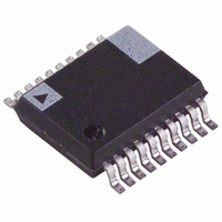
ADE7753ARS Analog Devices Inc, ADE7753ARS Datasheet - Page 23

ADE7753ARS
Manufacturer Part Number
ADE7753ARS
Description
IC ENERGY METERING DETEC 20-SSOP
Manufacturer
Analog Devices Inc
Specifications of ADE7753ARS
Rohs Status
RoHS non-compliant
Input Impedance
390 KOhm
Measurement Error
0.1%
Voltage - I/o High
2.4V
Voltage - I/o Low
0.8V
Current - Supply
3mA
Voltage - Supply
4.75 V ~ 5.25 V
Operating Temperature
-40°C ~ 85°C
Mounting Type
Surface Mount
Package / Case
20-SSOP (0.200", 5.30mm Width)
Meter Type
Single Phase
For Use With
EVAL-ADE7753ZEB - BOARD EVALUATION AD7753
Available stocks
Company
Part Number
Manufacturer
Quantity
Price
Part Number:
ADE7753ARS
Manufacturer:
ADI/亚德诺
Quantity:
20 000
Part Number:
ADE7753ARSZ
Manufacturer:
ADI/亚德诺
Quantity:
20 000
Part Number:
ADE7753ARSZRL
Manufacturer:
ADI/亚德诺
Quantity:
20 000
accumulation mode by setting the MSB of the MODE
register (MODE[15]).
off. Transitions in the direction of power flow, going from
negative to positive or positive to negative, set the IRQ pin
to active low if the Interrupt Enable register is enabled. The
Interrupt Status Registers, PPOS and PNEG, show which
transition has occurred. See ADE7753 Register Descriptions.
NO LOAD THRESHOLD
The ADE7753 includes a "no load threshold" feature that will
eliminate any creep effects in the meter.
accomplishes this by not accumulating energy if the multi-
plier output is below the "no load threshold". This threshold
is 0.001% of the full-scale output frequency of the multiplier.
Compare this value to the IEC1036 specification which states
that the meter must start up with a load equal to or less than
0.4% Ib. This standard translates to .0167% of the full-scale
output frequency of the multiplier.
REACTIVE POWER CALCULATION
Reactive power is defined as the product of the voltage and
current waveforms when one of this signal is phase shifted by
90º. The resulting waveform is called the instantaneous
reactive power signal. Equation 17 gives an expression for the
instantaneous reactive power signal in an ac system when the
phase of the current channel is shifted by +90º.
( i
Where
current channel, V = rms voltage and I = rms current.
Rp
Rp
The average power over an integral number of line cycles (n)
is given by the expression in Equation 18.
RP
where T is the line cycle period.
RP is referred to as the Reactive Power. Note that the reactive
power is equal to the DC component of the instantaneous
reactive power signal Rp(t) in Equation 17. This is the
relationship used to calculate reactive power in the ADE7753.
The instantaneous reactive power signal Rp(t) is generated by
multiplying the channel 1 and channel 2. In this case, the
phase of the channel 1 is shifted by +90º. The DC component
of the instantaneous reactive power signal is then extracted by
a low pass filter to obtain the reactive power information.
Figure 41 shows the signal processing in the Reactive Power
calculation in the ADE7753.
REV. PrF 10/02
v
) (
) t
t
(
(
t
t
)
)
nT
2
1
VI
v
2
I
(
is the phase difference between the voltage and
t
nT
sin(
sin(
0
)
V
Rp
sin(
i
) (
( '
) t
t
)
t
dt
)
VI
t
VI
( ' i
sin(
The default setting for this mode is
) t
sin(
)
2
t
PRELIMINARY TECHNICAL DATA
2
)
I
sin(
)
t
2
)
The ADE7753
(15)
(16)
(17)
(18)
–23–
The features of the Reactive Energy accumulation are the
same as the Line Active Energy accumulation. The number
of half line cycles is specified in the LINECYC register.
LINECYC is an unsigned 16-bit register. The ADE7754 can
accumulate Reactive Power for up to 65535 combined half
cycles. At the end of an energy calibration cycle the CYCEND
flag in the Interrupt Status register is set. If the CYCEND
mask bit in the Interrupt Mask register is enabled, the IRQ
output will also go active low. Thus the IRQ line can also be
used to signal the end of a calibration. The ADE7753
accumulates the Reactive Power signal in the LVARENERGY
register for an integer number of half cycles, as shown in
Figure 41.
The Reactive Energy accumulation in the ADE7753 not only
provides the reactive energy calculated using the phase shift
method, it is also useful to provide the sign of the reactive
power if it is desirable to use triangular method to calculate
reactive power. The ADE7753 also provides an accurate
measurement of the apparent power. The user can choose to
determine reactive energy through the mathematical rela-
tionship between apparent, active and reactive power. The
sign of the reactive energy can be found by reading the result
from the LVARENERGY register at the end of a reactive
energy accumulation cycle.
Re
APPARENT POWER CALCULATION
Apparent power is defined as the amplitude of the vector sum
of the Active and Reactive powers -see Figure 42. The angle
represents the phase shift due to non-resistive loads. For
single phase applications,
voltage and the current signals. Equation 20 gives an expres-
sion of the instantaneous power signal in an ac system with a
phase shift.
CHANNEL 2
between the Active Power and the Apparent Power generally
sign
active
FROM
ADC
(Re
Figure 41 - Reactive Power Signal Processing
LPF1
Energy
active
V
I
ZERO CROSS
Energy
DETECTION
90 DEGREE
PHASE SHIFT
2
MULTIPLIER
)
Instantaneous Reactive
Power Signal - Rp(t)
CALIBRATION
Apparent
LINECYC[14:0]
CONTROL
represents the angle between the
+
+
Energy
47
23
LVARENERGY[23:0]
ADE7753
2
0
Active
ACCUMULATE ACTIVE
ENERGY IN INTERNAL
REGISTER AND UPDATE
THE LVARENERGY
REGISTER AT THE END OF
LINECYC LINE CYCLES
Energy
0
2


