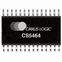
CS5464-ISZ Cirrus Logic Inc, CS5464-ISZ Datasheet - Page 24

CS5464-ISZ
Manufacturer Part Number
CS5464-ISZ
Description
IC ENERGY METERING 1PHASE 28SSOP
Manufacturer
Cirrus Logic Inc
Datasheet
1.CS5464-ISZ.pdf
(46 pages)
Specifications of CS5464-ISZ
Package / Case
28-SSOP
Input Impedance
30 KOhm
Measurement Error
0.1%
Voltage - I/o High
0.8V
Voltage - I/o Low
0.2V
Current - Supply
3.5mA
Voltage - Supply
4.75 V ~ 5.25 V
Operating Temperature
-40°C ~ 85°C
Mounting Type
Surface Mount
Meter Type
Single Phase
Output Voltage Range
2.4 V to 2.6 V
Input Voltage Range
2.4 V to 2.6 V
Input Current
100 nA
Power Dissipation
500 mW
Operating Temperature Range
- 40 C to + 85 C
Mounting Style
SMD/SMT
Input Voltage
5V
No. Of Outputs
3
Power Dissipation Pd
500mW
Supply Voltage Range
3.3V To 5V
No. Of Pins
28
Filter Terminals
SMD
Rohs Compliant
Yes
Lead Free Status / RoHS Status
Lead free / RoHS Compliant
For Use With
598-1554 - BOARD EVAL FOR CS5464 ADC
Lead Free Status / Rohs Status
Lead free / RoHS Compliant
Other names
598-1194-5
Available stocks
Company
Part Number
Manufacturer
Quantity
Price
Part Number:
CS5464-ISZ
Manufacturer:
CIRRUS
Quantity:
20 000
7.6 Commands
7.6.1 Conversion
7.6.2 Synchronization (SYNC0 and SYNC1)
7.6.3 Power Control (Stand-by, Sleep, Wake-up/Halt and Software Reset)
24
B7
B7
B7
1
1
1
CC
S[1:0]
All commands are 1 byte (8 bits) long. Many command values are unused and should NOT be written by the
application program. All commands except register reads, register writes, or synchronizing commands will
abort any conversion, calibration, or any initialization sequence currently executing. This includes reset. No
commands other than reads or synchronizing should be executed until the reset sequence completes.
Executes a conversion (measurement) program.
The serial interface is bidirectional. While reading data on the SDO output, the SDI input must be receiving
commands. If no command is needed during a read, SYNC0 or SYNC1 commands can be sent while read
data is received on SDO.
The serial port is normally initialized by de-asserting CS. An alternative method of initialization is to send 3 or
more SYNC1 commands followed by a SYNC0. This is useful in systems where CS is not used and tied low.
The CS5464 has two power-down states, stand-by and sleep. In stand-by, all circuitry except the voltage ref-
erence and clocks are turned off. In sleep, all circuitry except the command decoder is turned off. A
Wake-up/Halt command restores full-power operation after stand-by and issues a hardware reset after sleep.
The Software Reset command is a program that emulates a pin reset and is not a power control function.
B6
B6
B6
1
1
0
B5
B5
B5
S1
1
1
0 = Perform a Single Conversion (0xE0)
1 = Perform Continuous Conversion (0xE8)
01 = Sleep
10 = Wake-up/Halt
11 = Stand-by
Continuous/Single Conversion
00 = Software Reset
B4
B4
B4
S0
0
1
CC
B3
B3
B3
1
0
B2
B2
B2
0
1
0
B1
B1
B1
0
1
0
SYNC
B0
B0
B0
0
0
CS5464
DS682F1


