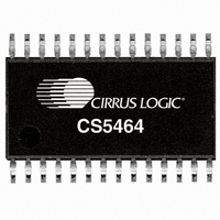
CS5464-ISZ Cirrus Logic Inc, CS5464-ISZ Datasheet - Page 16

CS5464-ISZ
Manufacturer Part Number
CS5464-ISZ
Description
IC ENERGY METERING 1PHASE 28SSOP
Manufacturer
Cirrus Logic Inc
Datasheet
1.CS5464-ISZ.pdf
(46 pages)
Specifications of CS5464-ISZ
Package / Case
28-SSOP
Input Impedance
30 KOhm
Measurement Error
0.1%
Voltage - I/o High
0.8V
Voltage - I/o Low
0.2V
Current - Supply
3.5mA
Voltage - Supply
4.75 V ~ 5.25 V
Operating Temperature
-40°C ~ 85°C
Mounting Type
Surface Mount
Meter Type
Single Phase
Output Voltage Range
2.4 V to 2.6 V
Input Voltage Range
2.4 V to 2.6 V
Input Current
100 nA
Power Dissipation
500 mW
Operating Temperature Range
- 40 C to + 85 C
Mounting Style
SMD/SMT
Input Voltage
5V
No. Of Outputs
3
Power Dissipation Pd
500mW
Supply Voltage Range
3.3V To 5V
No. Of Pins
28
Filter Terminals
SMD
Rohs Compliant
Yes
Lead Free Status / RoHS Status
Lead free / RoHS Compliant
For Use With
598-1554 - BOARD EVAL FOR CS5464 ADC
Lead Free Status / Rohs Status
Lead free / RoHS Compliant
Other names
598-1194-5
Available stocks
Company
Part Number
Manufacturer
Quantity
Price
Part Number:
CS5464-ISZ
Manufacturer:
CIRRUS
Quantity:
20 000
4.8 Power and Energy Results
The instantaneous voltage and current samples are
multiplied to obtain the instantaneous power ( P1 , P2 )
(see
N conversions to compute active power ( P1
P2
Apparent power ( S1 , S2 ) is the product of RMS voltage
and current as shown:
Power factor ( PF1 , PF2 ) is active power divided by ap-
parent power as shown below. The sign of the power
factor is determined by the active power.
Wideband reactive power ( Q1
by doing a vector subtraction of active power from ap-
parent power.
Quadrature power ( Q1 , Q2 ) are sample rate results ob-
tained by multiplying instantaneous current ( I1 , I2 ) by in-
stantaneous quadrature voltage ( V1Q , V2Q ) which are
created by phase shifting instantaneous voltage ( V1 ,
V2 ) 90 degrees using first-order integrators. (see
3
16
and 4). The gain of these integrators is inversely relat-
AVG
Figure 3
).
P1
OFF
(P2
and 4). The product is then averaged over
OFF
Q
)
S
WB
PF
=
=
V
=
RMS
P
----------------------
S
ACTIVE
2
×
S
–
WB
I
P
RMS
ACTIVE
2
, Q2
WB
Figure 5. Low-rate Calculations
) is calculated
(V2
V1
(I2
I1
Figure
ACOFF
ACOFF
ACOFF
ACOFF
AVG
)
)
,
ed to line frequency, so their gain is corrected by the Ep-
silon register, which is based on line frequency.
Reactive power ( Q1
grating the instantaneous quadrature power over N
samples.
4.9 Peak Voltage and Current
Peak current ( I1
( V1
samples detected in the previous low-rate interval.
4.10 Power Offset
The power offset registers, P1
to offset erroneous power sources resident in the sys-
tem not originating from the power line. Residual power
offsets are usually caused by crosstalk into current
paths from voltage paths or from ripple on the meter or
chip’s power supply, or from inductance from a nearby
transformer.
These offsets can be either positive or negative, indicat-
ing crosstalk coupling either in phase or out of phase
with the applied voltage input. The power offset regis-
ters can compensate for either condition.
To use this feature, measure the average power at no
load using either Single or Continuous Conversion com-
mands. Take the measured result (from the P1
( P2
to the associated power offset register, P1
PEAK
AVG
) register), invert (negate) the value and write it
, V2
PEAK
) are the largest current and voltage
PEAK
AVG
, I2
, Q2
PEAK
AVG
OFF
) is generated by inte-
) and peak voltage
( P2
OFF
) can be used
CS5464
OFF
DS682F1
( P2
OFF
AVG
).


