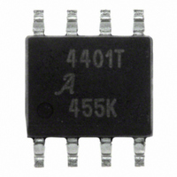
A4401KL-T Allegro Microsystems Inc, A4401KL-T Datasheet - Page 8

A4401KL-T
Manufacturer Part Number
A4401KL-T
Description
IC QUASI FLYBACK CONVERTER 8SOIC
Manufacturer
Allegro Microsystems Inc
Datasheet
1.A4401KLTR-T.pdf
(17 pages)
Specifications of A4401KL-T
Display Type
Vacuum Fluorescent (VF)
Current - Supply
2.3mA
Voltage - Supply
7 V ~ 40 V
Operating Temperature
-40°C ~ 125°C
Mounting Type
Surface Mount
Package / Case
8-SOIC (3.9mm Width)
Lead Free Status / RoHS Status
Lead free / RoHS Compliant
Interface
-
Configuration
-
Digits Or Characters
-
A4401
Switching Turn-On Losses
determined by the amount of energy the resonant
capacitor, C11, has to discharge into the MOSFET. At
low battery voltage, the resonant swing should force
the volts across the capacitor to only a few volts, mak-
ing this loss negligible.
Total Losses
estimated as follows:
The thermal resistance, R
two methods. One is by estimating a maximum junc-
tion temperature, T
operating junction temperature, using the given device
package mounted on a printed circuit board with cop-
per trace area connected to the device. R
calculated as follows:
The drain-to-source rating, V
the maximum input voltage, V
reflected output voltage. Adequate margin should also
be added, to allow for tolerancing effects and parasitic
voltage ring. It can be calculated as follows:
D2, D3, and D4 Output Diodes Selection
For the low voltage outputs such as the filament sup-
ply, it is recommended that a Schottky diode be used.
For the higher voltage rails, ultrafast rectifier diodes
are recommended.
For each output, estimate the maximum reverse volt-
age, V
diode is subjected to. The V
RRM
V
DS
, and the maximum average current that the
=
The total MOSFET power loss can be
⎛
⎜ ⎜
⎝
P
R
V
TOTAL
θJA
OUT
J
=
(max). The other is to test for the
×
=
T
P
N
J
TOTAL
N
OUT
P
– T
P
STATIC
θJA
A
⎞
⎟ ⎟
⎠
RRM
, can be determined by
+ V
DS
The turn-on losses are
BAT
+ P
Automotive Quasi-Resonant Flyback Control IC
, is the sum of
BAT
.
rating should exceed
TURNOFF
(max), plus the
(max)
θJA
.
.
is then
(12)
(13)
(11)
at least 20% of the maximum V
lated as follows:
The maximum average current through the diode is
simply the maximum load current. The diode should
be rated to handle this current with some margin.
In addition, the diode should be able to handle the
power dissipation. The majority of the power loss is
simply the static loss:
The forward voltage drop, V
diode characteristics at maximum load.
C1 Input Capacitor Selection
In the interests of cost and performance, it is recom-
mended that ultralow impedance electrolytic capaci-
tors be used. The ratio of the source impedance to the
impedance of the input capacitor will determine how
much of the input current is drawn from the input
capacitor. For example, if the source impedance is
relatively high, then the input capacitor would have
to supply the triangular current that flows through the
primary winding, the MOSFET Q1, and the current
sense resistor. This rms current was worked out in the
Current Sense Resistor Selection section.
Electrolytic capacitors experience heating effects
caused by the rms current flowing through the ESR
of the device. The maximum rms current is normally
quoted at 100 kHz and 105°C. Frequency correc-
tion factors for the ripple current are provided when
the operating frequencies are less than 100 kHz. A
50 VDC rating should be adequate for most applica-
tions.
C4, C6, and C8 Output Capacitors Selection
The overall equivalent capacitance on the output
should not be less 22 μF (see Control Loop section
V
DIODE
P
=
STATIC
V
BAT
=
(max) ×
115 Northeast Cutoff, Box 15036
Allegro MicroSystems, Inc.
Worcester, Massachusetts 01615-0036 (508) 853-5000
www.allegromicro.com
V
f
× I
f
LOAD
, can be found from the
N
N
DIODE
S1
P
.
+ V
voltage, calcu-
OUT
.
(14)
(15)
8


