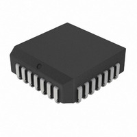
TC14433ELI Microchip Technology, TC14433ELI Datasheet - Page 10

TC14433ELI
Manufacturer Part Number
TC14433ELI
Description
IC ADC 3 1/2 DIGIT 28PLCC
Manufacturer
Microchip Technology
Specifications of TC14433ELI
Display Type
LED
Configuration
7 Segment
Interface
BCD
Digits Or Characters
A/D 3.5 Digits
Current - Supply
1.8mA
Voltage - Supply
4.5 V ~ 8 V
Operating Temperature
-40°C ~ 85°C
Mounting Type
Surface Mount
Package / Case
28-PLCC
Lead Free Status / RoHS Status
Lead free / RoHS Compliant
Available stocks
Company
Part Number
Manufacturer
Quantity
Price
Company:
Part Number:
TC14433ELI
Manufacturer:
MICROCHIP
Quantity:
12 000
Company:
Part Number:
TC14433ELI
Manufacturer:
Microchip Technology
Quantity:
10 000
Company:
Part Number:
TC14433ELI713
Manufacturer:
MICROCHIP
Quantity:
12 000
Company:
Part Number:
TC14433ELI713
Manufacturer:
Microchip Technology
Quantity:
10 000
TC14433/A
5.0
The typical application circuit is an example of a 3-1/2
digit voltmeter using the TC14433 with Common-
anode displays. This system requires a 2.5V reference.
Full scale may be adjusted to 1.999V or 199.9 mV.
Input overrange is indicated by flashing a display. This
display uses LEDs with common anode digit lines.
Power supply for this system is shown as a dual ±5V
supply; however, the TC14433 will operate over a wide
voltage range
The circuit in
voltmeter. The 14024B provides the low frequency
square wave signal drive to the LCD backplane. Dual
power supplies are shown here; however, one supply
may be used when V
case, V
When only segments b and c of the decoder are con-
nected to the 1/2 digit of the display, 4, 0, 7 and 3
appear as 1.
The overrange indication (Q
when the count is greater than 1999; (e.g., 1.999V for
a reference of 2V) The underrange indication, useful for
auto-ranging circuits, occurs when the count is less
than 180; (e.g., 0.180V for a reference of 2V).
DS21394D-page 10
Note:
AG
TYPICAL APPLICATIONS
must be at least 2.8V above V
If the most significant digit is connected to
a display other than a “1” only, such as a
full digit display, segments other than b
and c must be disconnected. The BCD to
7-segment decoder must blank on BCD
inputs 1010 to 1111 (see
Figure 5-1
SS
is connected to V
shows a 3-1/2 digit LCD
3
= 0 and Q
Table
EE
0
= 1) occurs
.
EE
5-1).
. In this
TABLE 5-1:
Figure 5-2
with a minimum of external components, (only 11
additional components). In this circuit, the 14511B
provides the segment drive and the 75492 or 1413
provides sink for digit current. Display is blanked during
the overrange condition.
Condition
Note 1:
of MSD
Coded
+0 UR
+1 OR
-0 UR
-1 OR
+0
+1
-0
-1
is an example of a 3-1/2 digit LED voltmeter
Q
Q
Q
When used in conjunction with Q
of out of range condition is indicated; i.e.,
Q
3
2
0
3
Q
1
1
1
1
0
0
0
0
3
– 1/2 digit, low for “1”, high for “0”.
– Out of range condition exists if Q
– Polarity: “1” = positive, “0” = negative.
= 0 → OR or Q
Q
1
0
1
0
1
0
1
0
2
TRUTH TABLE
Q
1
1
1
1
0
0
1
1
1
© 2008 Microchip Technology Inc.
Q
0
0
1
1
0
0
1
1
0
3
4 – 1
0 – 1
7 – 1
3 – 1
= 1 → UR.
BDC to 7-Segment
Decoding
b and c to MSD
only segments
Blank
Blank
Blank
Blank
Hook up
3
, the type
0
= 1.


