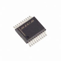
MAX745EAP+ Maxim Integrated Products, MAX745EAP+ Datasheet - Page 6

MAX745EAP+
Manufacturer Part Number
MAX745EAP+
Description
IC BATTERY CHARGER LI+ 20-SSOP
Manufacturer
Maxim Integrated Products
Datasheet
1.MAX745EAP.pdf
(8 pages)
Specifications of MAX745EAP+
Function
Charge Management
Battery Type
Lithium-Ion (Li-Ion)
Voltage - Supply
6 V ~ 24 V
Operating Temperature
-40°C ~ 85°C
Mounting Type
Surface Mount
Package / Case
20-SSOP
Output Voltage
5.4 V
Operating Supply Voltage
6 V to 24 V
Supply Current
4 mA
Maximum Operating Temperature
+ 85 C
Minimum Operating Temperature
- 40 C
Mounting Style
SMD/SMT
Lead Free Status / RoHS Status
Lead free / RoHS Compliant
Switch-Mode Lithium-Ion
Battery Charger
V
battery cell count.
The battery limit voltage is set by the following:
Solving for V
Set V
and determine R3 by:
Table 1. Cell-Count Programming Table
Figure 1. Standard Application Circuit
6
V
REF
BATT
_______________________________________________________________________________________
0.1µF
ADJ
C4
/ 2, the voltage limit is 4.2V. Table 1 defines the
CELL0
GND
GND
VL
VL
= cell count x V
V
100kΩ
ADJ
by choosing a value for R11 (typically 100kΩ),
100kΩ
(
R11
1%
1%
R3 = [1 - (V
R3
ADJ
=
, we get:
9.523 V
(
cell count
R12
R16
)
ADJ
CELL1
BATT
GND
GND
REF
VL
VL
C2, 0.1µF
4.7µF
/ V
)
10kΩ
THM 1
C5
R15
V
REF
IN
+
−
9.023V
)] x R11 (Figure 1)
10kΩ
47nF
(UP TO 24V)
R2
C3
V
ADJ
CELL COUNT
REF
9.523
REF
THM/SHDN
SETI
VADJ
CCV
CCI
−
2
1
1
2
3
4
V
REF
VL
MAX745
GND
DCIN
IBAT
where V
The voltage-regulation loop is compensated at the CCV
pin. Typically, a series-resistor-capacitor combination
can be used to form a pole-zero doublet. The pole
introduced rolls off the gain starting at low frequencies.
The zero of the doublet provides sufficient AC gain at
mid-frequencies. The output capacitor (C1) rolls off the
mid-frequency gain to below unity. This guarantees sta-
bility before encountering the zero introduced by the
C1’s equivalent series resistance (ESR). The GMV
amplifier’s output is internally clamped to between one-
fourth and three-fourths of the voltage at REF.
The charging current is set by a combination of the cur-
rent-sense resistor value and the SETI pin voltage. The
current-sense amplifier measures the voltage across
the current-sense resistor, between CS and BATT. The
current-sense amplifier’s gain is 6. The voltage on SETI
is buffered and then divided by 4. This voltage is com-
pared to the current-sense amplifier’s output.
Therefore, full-scale current is accomplished by con-
necting SETI to REF. The full-scale charging current
(I
FS)
STATUS
PGND
BATT
DLO
BST
DHI
CS
LX
is set by the following:
IN4148
REF
I
FS
= 4.2V and cell count is 1, 2, 3, 4 (Table 1).
D2
1/2 IRF7303
= 185mV / R1 (Figure 1)
C7
0.1µF
M1B
C6
0.1µF
1/2 IRF7303
M1A
D1
MBRS
340T3
22µH
L1
Current Control
BATTERY
D6
MBRS
340T3
R1
0.2Ω
C1
68µF


