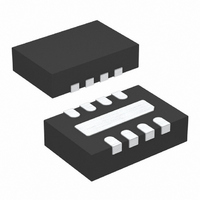
LTC4068XEDD-4.2 Linear Technology, LTC4068XEDD-4.2 Datasheet - Page 8

LTC4068XEDD-4.2
Manufacturer Part Number
LTC4068XEDD-4.2
Description
IC CHARGER BATT LI-ON 8-DFN
Manufacturer
Linear Technology
Type
Battery Chargerr
Datasheet
1.LTC4068EDD-4.2PBF.pdf
(12 pages)
Specifications of LTC4068XEDD-4.2
Function
Charge Management
Battery Type
Lithium-Ion (Li-Ion)
Voltage - Supply
4.25 V ~ 6.5 V
Operating Temperature
-40°C ~ 85°C
Mounting Type
Surface Mount
Package / Case
8-WFDFN Exposed Pad
Output Current
950mA
Output Voltage
4.2V
Operating Supply Voltage (min)
4.25V
Operating Supply Voltage (max)
6.5V
Operating Temp Range
-40C to 85C
Package Type
DFN
Mounting
Surface Mount
Pin Count
8
Operating Temperature Classification
Industrial
Lead Free Status / RoHS Status
Contains lead / RoHS non-compliant
Lead Free Status / RoHS Status
Contains lead / RoHS non-compliant
Available stocks
Company
Part Number
Manufacturer
Quantity
Price
Company:
Part Number:
LTC4068XEDD-4.2
Manufacturer:
LT
Quantity:
10 000
Part Number:
LTC4068XEDD-4.2
Manufacturer:
LINEAR/凌特
Quantity:
20 000
Company:
Part Number:
LTC4068XEDD-4.2#PBF
Manufacturer:
LINEAR
Quantity:
116
Part Number:
LTC4068XEDD-4.2#PBF
Manufacturer:
LT/凌特
Quantity:
20 000
Company:
Part Number:
LTC4068XEDD-4.2#TRPBF
Manufacturer:
LT
Quantity:
7 480
OPERATIO
Charge Status Indicator (CHRG)
The charge status output has two states: pull-down and
high impedance. The pull-down state indicates that the
LTC4068 is in a charge cycle. Once the charge cycle has
terminated or the LTC4068 is disabled, the pin state
becomes high impedance.
Power Supply Status Indicator (ACPR)
The power supply status output has two states: pull-down
and high impedance. The pull-down state indicates that
V
above the battery voltage. If these conditions are not met,
the ACPR pin is high impedance indicating that the LTC4068
is unable to charge the battery.
LTC4068-4.2/LTC4068X-4.2
threshold (V
charge current is once again supplied to the battery. To
manually restart a charge cycle when in standby mode, the
input voltage must be removed and reapplied or the charger
must be shut down and restarted using the EN pin. Figure 1
shows the state diagram of a typical charge cycle.
8
POWER ON
UVLO CONDITION
CC
EN DRIVEN LOW
is above the UVLO threshold (3.8V) and is also 100mV
I
Figure 1. State Diagram of a Typical Charge Cycle
CC
SHUTDOWN MODE
STOPS
DROPS TO <25µA
CHRG: Hi-Z
OR
RECHRG
UVLO CONDITION
EN DRIVEN HIGH
U
OR
), another charge cycle begins and
1/10TH FULL CURRENT
NO CHARGE CURRENT
TRICKLE CHARGE
STANDBY MODE
CHRG: STRONG
CHRG: STRONG
CHRG: Hi-Z
CHARGE MODE
FULL CURRENT
406842 F01
MODE
PULL-DOWN
PULL-DOWN
BAT < 2.9V
BAT > 2.9V
ITERM < 100mV
2.9V < BAT < 4.1V
BAT > 2.9V
LTC4068
ONLY
Thermal Limiting
An internal thermal feedback loop reduces the programmed
charge current if the die temperature attempts to rise above
a preset value of approximately 120°C. This feature protects
the LTC4068 from excessive temperature and allows the
user to push the limits of the power handling capability of
a given circuit board without risk of damaging the LTC4068.
The charge current can be set according to typical (not worst
case) ambient temperature with the assurance that the
charger will automatically reduce the current in worst-case
conditions. DFN power considerations are discussed fur-
ther in the Applications Information section.
Undervoltage Lockout (UVLO)
An internal undervoltage lockout circuit monitors the input
voltage and keeps the charger in shutdown mode until V
rises above the undervoltage lockout threshold. The UVLO
circuit has a built-in hysteresis of 200mV. Furthermore, to
protect against reverse current in the power MOSFET, the
UVLO circuit keeps the charger in shutdown mode if V
falls to within 30mV of the BAT voltage. If the UVLO com-
parator is tripped, the charger will not come out of shut-
down mode until V
Manual Shutdown
At any point in the charge cycle, the LTC4068 can be put
into shutdown mode by driving the EN pin high. This
reduces the battery drain current to less than 2µA and the
supply current to less than 50µA. When in shutdown
mode, the CHRG pin is in the high impedance state. A new
charge cycle can be initiated by driving the EN pin low. An
internal resistor pull-down on this pin forces the LTC4068
to be enabled if the pin is allowed to float.
Automatic Recharge
Once the charge cycle is terminated, the LTC4068 continu-
ously monitors the voltage on the BAT pin using a com-
parator with a 2ms filter time (t
restarts when the battery voltage falls below 4.10V (which
corresponds to approximately 80% to 90% battery capac-
ity). This ensures that the battery is kept at, or near, a fully
CC
rises 100mV above the BAT voltage.
RECHARGE
). A charge cycle
406842fa
CC
CC


