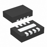
LTC4068XEDD-4.2 Linear Technology, LTC4068XEDD-4.2 Datasheet - Page 5

LTC4068XEDD-4.2
Manufacturer Part Number
LTC4068XEDD-4.2
Description
IC CHARGER BATT LI-ON 8-DFN
Manufacturer
Linear Technology
Type
Battery Chargerr
Datasheet
1.LTC4068EDD-4.2PBF.pdf
(12 pages)
Specifications of LTC4068XEDD-4.2
Function
Charge Management
Battery Type
Lithium-Ion (Li-Ion)
Voltage - Supply
4.25 V ~ 6.5 V
Operating Temperature
-40°C ~ 85°C
Mounting Type
Surface Mount
Package / Case
8-WFDFN Exposed Pad
Output Current
950mA
Output Voltage
4.2V
Operating Supply Voltage (min)
4.25V
Operating Supply Voltage (max)
6.5V
Operating Temp Range
-40C to 85C
Package Type
DFN
Mounting
Surface Mount
Pin Count
8
Operating Temperature Classification
Industrial
Lead Free Status / RoHS Status
Contains lead / RoHS non-compliant
Lead Free Status / RoHS Status
Contains lead / RoHS non-compliant
Available stocks
Company
Part Number
Manufacturer
Quantity
Price
Company:
Part Number:
LTC4068XEDD-4.2
Manufacturer:
LT
Quantity:
10 000
Part Number:
LTC4068XEDD-4.2
Manufacturer:
LINEAR/凌特
Quantity:
20 000
Company:
Part Number:
LTC4068XEDD-4.2#PBF
Manufacturer:
LINEAR
Quantity:
116
Part Number:
LTC4068XEDD-4.2#PBF
Manufacturer:
LT/凌特
Quantity:
20 000
Company:
Part Number:
LTC4068XEDD-4.2#TRPBF
Manufacturer:
LT
Quantity:
7 480
PI FU CTIO S
ITERM (Pin 1): Charge Termination Program. The charge
termination current threshold current is programmed by
connecting a 1% resistor, R
threshold I
BAT (Pin 2): Charge Current Output. Provides charge
current to the battery from the internal P-channel MOSFET,
and regulates the final float voltage to 4.2V. An internal
precision resistor divider from this pin sets the float
TYPICAL PERFOR A CE CHARACTERISTICS
U
I
TERM
=
U
TERM
R
100
TERM
, is set by the following formula:
V
600
500
400
300
200
100
700
650
600
550
500
450
400
350
0
–50
,
4
Power FET “ON” Resistance
vs Temperature
U
Charge Current vs Supply Voltage
R
V
T
θ
V
I
R
BAT
A
BAT
JA
CC
PROG
TERM
= 25°C
–25
= 40°C/W
= 4.2V
= 100mA
= 4V
4.5
= 2k
W
=
TERM
0
TEMPERATURE (°C)
5
I
100
TERM
R
R
PROG
25
PROG
V
, to ground. The current
CC
U
5.5
V
(V)
= 10k
= 2k
50
6
75
6.5
100
405842 G13
405842 G17
125
7
voltage. This divider is disconnected in shutdown mode to
minimize current drain from the battery.
CHRG (Pin 3): Charge Status Open-Drain Output. When
the battery is charging, the CHRG pin is pulled low by an
internal N-channel MOSFET. When the charge cycle is
completed, CHRG becomes high impedance.
GND (Pins 4, 9): Ground/Exposed Pad. The exposed
backside package pad (Pin 9) is electrical ground and
must be soldered to the PC board for maximum heat
transfer.
4.16
4.14
4.06
4.04
4.12
4.10
4.08
600
500
400
300
200
100
0
–50
–50
LTC4068-4.2/LTC4068X-4.2
Recharge Threshold Voltage
vs Temperature
Charge Current
vs Ambient Temperature
V
R
V
V
θ
CC
PROG
CC
BAT
JA
–25
= 5V
–25
= 40°C/W
ONSET OF THERMAL REGULATION
= 5V
= 4V
= 10k
0
TEMPERATURE (°C)
TEMPERATURE (°C)
0
R
R
PROG
PROG
25
25
= 10k
= 2k
50
50
75
75
100
405842 G14
405842 G15
100
125
406842fa
5


