DS2756E+ Maxim Integrated Products, DS2756E+ Datasheet - Page 15

DS2756E+
Manufacturer Part Number
DS2756E+
Description
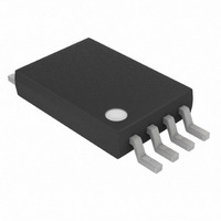
IC FUEL GAUGE BATT 8TSSOP
Manufacturer
Maxim Integrated Products
Datasheet
1.DS2756E.pdf
(27 pages)
Specifications of DS2756E+
Function
Fuel, Gas Gauge/Monitor
Battery Type
Lithium-Ion (Li-Ion), Lithium-Polymer (Li-Pol)
Voltage - Supply
3 V ~ 5.5 V
Operating Temperature
-40°C ~ 85°C
Mounting Type
Surface Mount
Package / Case
8-TSSOP
Operating Supply Voltage
3 V to 5.5 V
Supply Current
75 uA
Maximum Operating Temperature
+ 85 C
Minimum Operating Temperature
- 40 C
Charge Safety Timers
Yes
Mounting Style
SMD/SMT
Temperature Monitoring
Yes
Lead Free Status / RoHS Status
Lead free / RoHS Compliant
DS2756: High-Accuracy Battery Fuel Gauge with Programmable Suspend Mode
SNAPSHOT MODE
Measurement of the current and voltage can be synchronized to a system event with the Snapshot mode.
Triggering a Snapshot event causes the ADC to abandon the current conversion and capture one current and one
voltage sample. The Snapshot results are reported in the Current and Voltage registers for retrieval by the host.
Normal current, voltage and temperature measurements and current accumulation resume immediately following a
Snapshot event, though the Snapshot current and voltage values persist until the host system writes the SNAP bit
in the Special Function Register to a 0. Since the snapshot mode disrupts the continuity of the coulomb counting
process, it should be used sparingly.
The Sync Function Command [D2h] signals the ADC control to expect a Snapshot trigger on DQ. Following the
Sync command, the host can trigger a Snapshot event by toggling the DQ line. Synchronization occurs on the
rising edge of the DQ high to low to high pulse. The Snapshot mode can be abandoned by sending a 1-Wire Reset
instead of the synchronization pulse. The rising edge DQ trigger is formed by the first data bit after issuing the Sync
Function command. A full byte can be issued, but the rising edge of the first bit sets the trigger point. The SNAP bit
is set after the rising edge trigger. Timing is not critical and could be several 100s later since it cannot be read
quickly via 1-Wire. If a 1-Wire reset is issued instead of a data bit, then the Snapshot is abandoned (SNAP bit not
set).
The Snapshot Synchronization Timing in Figure 13 illustrates the timing of the Snapshot current and voltage
sample apertures relative to the DQ rising edge trigger and one timeslot GSM power amp load pulse. In the
-1
diagram, t
= 1/ f
= 1456
= 687s. The current and voltage measurements are taken 343s apart but within
SAMP
SAMP
a single GSM timeslot.
Figure 13. Snapshot Synchronization Timing
15 of 27


