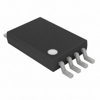
DS2756E+ Maxim Integrated Products, DS2756E+ Datasheet - Page 10

DS2756E+
Manufacturer Part Number
DS2756E+
Description
IC FUEL GAUGE BATT 8TSSOP
Manufacturer
Maxim Integrated Products
Datasheet
1.DS2756E.pdf
(27 pages)
Specifications of DS2756E+
Function
Fuel, Gas Gauge/Monitor
Battery Type
Lithium-Ion (Li-Ion), Lithium-Polymer (Li-Pol)
Voltage - Supply
3 V ~ 5.5 V
Operating Temperature
-40°C ~ 85°C
Mounting Type
Surface Mount
Package / Case
8-TSSOP
Operating Supply Voltage
3 V to 5.5 V
Supply Current
75 uA
Maximum Operating Temperature
+ 85 C
Minimum Operating Temperature
- 40 C
Charge Safety Timers
Yes
Mounting Style
SMD/SMT
Temperature Monitoring
Yes
Lead Free Status / RoHS Status
Lead free / RoHS Compliant
DS2756: High-Accuracy Battery Fuel Gauge with Programmable Suspend Mode
PROGRAMMABLE I/O
The PIO pin can be configured as a general purpose programmable I/O pin, or as an interrupt output. To use the
PIO pin in the programmable I/O mode described in this section, the PIO interrupt method must not be enabled.
See the Interrupt Signaling section for information on disabling interrupts.
As a programmable I/O pin, PIO provides a digital input or an open drain digital output. Writing a 1 to the PIO bit in
the Special Feature Register disables the output driver. With the PIO pin Hi-Z, it can be used as an input. The logic
level of the PIO pin is reported in the Special Feature Register through the serial interface.
To use the PIO pin as an output, write the desired output value to the PIO bit in the Special Feature Register.
Writing a 0 to the PIO bit enables the PIO output driver, pulling the PIO pin to V
. As stated above, writing a 1 to
SS
the PIO bit forces the pin to a Hi-Z state. A pullup resistor or current source must be provided to force the pin high.
The PIO pin can be biased several volts above VDD allowing inter-operation with a system voltage which is higher
than the battery voltage. Consult the Absolute Maximum Ratings table when operating the PIO pin significantly
above VDD. The DS2756 turns off the PIO output driver and sets the PIO bit high when in Sleep mode or when DQ
is low for more than t
, regardless of the state of the PMOD bit.
SLEEP
INTERRUPT SIGNALING
The DS2756 interrupt can be configured as the Suspend interrupt that is signaled on the PIO pin, or as an Alarm
Comparator interrupt (based on Current Accumulator and Temperature Alarm Comparator thresholds) that is
signaled on either the PIO pin or DQ pin.
The Suspend interrupt is used to signal that the current level is greater than the user programmable Charge
Suspend Threshold or less than (more negative) than the Discharge Suspend Threshold. The Suspend interrupt is
enabled by setting one or both of the PIE bits in the Status Register. The PIE bits select one of three intervals for
the Suspend Period, t
. If either PIE bit is set, the Alarm Comparator interrupt is disabled. The Suspend interrupt
SUS
event is signaled by internally clearing the PIO bit in the SFR in order to force the PIO output from high to low. The
PIO output remains low in Active mode until the PIO bit in the SFR is written to a 1 by the host to disable the PIO
output. Note that the PIO output is disabled in Suspend mode, allowing the PIO pin to be pulled high and ensuring
the DS2756 can always signal a Suspend interrupt with a high to low transition.
The Temperature and ACR Alarm Comparator interrupt is enabled by setting the Interrupt Enable (IE) bit in the
Special Feature Register with PIE cleared. When IE is set and both PIE bits are cleared, an interrupt will be
signaled if the Alarm Comparator thresholds are crossed. A 1-Wire RESET always clears the IE bit. The host must
re-enable interrupts by setting IE in the last transaction on the bus. Note that when either PIE bit is set, the state of
IE has no effect.
The interrupt signal pin for the Alarm Comparator interrupt is selected by setting or clearing the Interrupt Output
Select (IOS) bit in the Status Register. When IOS is set, the DQ pin performs Alarm Comparator interrupt signaling,
when IOS is cleared, the PIO pin performs Alarm Comparator interrupt signaling. Note that when either PIE bit is
set, the state of IOS has no effect.
DQ signals an Alarm Comparator interrupt condition by driving the 1-Wire bus low for t
. The DS2756 and all other
IL
1-Wire devices present on the bus interpret this signal as a 1-Wire RESET. A Presence Pulse should be expected
from all 1-Wire devices, including the DS2756 following the alarm interrupt signal. The host system can sense the
alarm interrupt signal on the falling or rising edge of either the RESET or Presence Pulse.
PIO signals an Alarm Comparator interrupt by driving low. PIO remains low until the host clears the condition by
writing a 1 to the PIO bit (bit 6 in the Special Feature Register). A pullup resistor or current source must be
provided to force the pin high. The host must sense the alarm interrupt on the falling edge of PIO.
10 of 27


