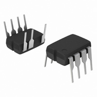
NCP1028P065G ON Semiconductor, NCP1028P065G Datasheet - Page 11

NCP1028P065G
Manufacturer Part Number
NCP1028P065G
Description
IC SWIT HV 8DIP
Manufacturer
ON Semiconductor
Datasheet
1.NCP1028P065G.pdf
(29 pages)
Specifications of NCP1028P065G
Output Isolation
Isolated
Frequency Range
58.5 ~ 71.5kHz
Voltage - Input
7.2 ~ 10 V
Voltage - Output
700V
Power (watts)
25W
Operating Temperature
0°C ~ 150°C
Package / Case
8-DIP (0.300", 7.62mm), 7 Leads
Lead Free Status / RoHS Status
Lead free / RoHS Compliant
Available stocks
Company
Part Number
Manufacturer
Quantity
Price
Part Number:
NCP1028P065G
Manufacturer:
ON/安森美
Quantity:
20 000
Startup Sequence
directly deriving current from the bulk line to charge the
outlet, the internal current source is biased and charges up
the V
reaches the VCC
source turns off, reducing the amount of power being
dissipated. At this time, the V
controller, and the auxiliary supply should take over before
V
must therefore be calculated to hold enough energy so that
V
auxiliary voltage fully takes over.
order to self-supply the switcher. The V
CC
CC
The NCP1028 includes a high-voltage startup circuitry,
When the power supply is first connected to the mains
An auxiliary winding is needed to maintain the V
collapses below VCC
CC
stays above VCC
capacitor. When the voltage on this V
ON
level (typically 8.5 V), the current
Vbulk
(min)
(min)
CC
. This V
(7.3 V typical) until the
+
Figure 23. Internal Arrangement of the Startup Circuitry
I1
I2
capacitor only supplies the
RV
CV
CC
CC
1
CC
CC
capacitor, CV
capacitor has
CC
Vz = 8.7 V
I
clamp
capacitor
ICC1
http://onsemi.com
CC
CC
NCP1028
in
,
11
V
arrangement.
only a supply role and its value does not impact other
parameters such as fault duration or the frequency sweep
period for instance. As one can see in Figure 23, an internal
active Zener diode, protects the switcher against lethal V
runaways. This situation can occur if the feedback loop
optocoupler fails, for instance, and you would like to
protect the converter against an over voltage event.
amount of energy that needs to be stored; b) the time it
takes for the auxiliary voltage to appear, and; c) the current
consumed by the controller at that time. For a better
understanding, Figure 24 shows how the voltage evolves
on the V
V
V
CC
CCon
CCoff
The V
-
IC1
←
capacitor. Figure 23 details the simplified internal
+
+
CC
+
CC
capacitor upon startup.
capacitor can be calculated knowing a) the
5
8
CC


