LNK354GN Power Integrations, LNK354GN Datasheet - Page 5
LNK354GN
Manufacturer Part Number
LNK354GN
Description
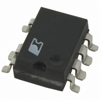
IC OFFLINE SWIT OCP HV 8SMD
Manufacturer
Power Integrations
Series
LinkSwitch®-HFr
Type
Off Line Switcherr
Datasheet
1.LNK353GN-TL.pdf
(16 pages)
Specifications of LNK354GN
Output Isolation
Isolated
Frequency Range
186 ~ 214kHz
Voltage - Output
700V
Power (watts)
5W
Operating Temperature
-40°C ~ 150°C
Package / Case
8-SMD Gull Wing, 7 Leads
Output Voltage
5.8 V
Input / Supply Voltage (max)
265 VAC
Input / Supply Voltage (min)
85 VAC
Duty Cycle (max)
63 %
Switching Frequency
200 KHz
Supply Current
280 uA
Operating Temperature Range
- 40 C to + 150 C
Mounting Style
SMD/SMT
Lead Free Status / RoHS Status
Lead free / RoHS Compliant
Available stocks
Company
Part Number
Manufacturer
Quantity
Price
Company:

Part Number:
LNK354GN
Manufacturer:
POWER
Quantity:
15 000


Key Application Considerations
LinkSwitch-HF Design Considerations
Output Power Table
Data sheet maximum output power table (Table 1) represents
the maximum practical continuous output power level that can
be obtained under the following assumed conditions:
1. The minimum DC input voltage is 90 V or higher for 85 VAC
2. Secondary output of 5.5 V with a Schottky rectifier diode.
3. Assumed efficiency of 70%.
4. Operating frequency of f
5. Voltage only output (no secondary side constant current
6. Continuous mode operation (0.6 ≤ K
7. The part is board mounted with SOURCE pins soldered
8. Ambient temperature of 50 °C for open frame designs
Below a value of 1, K
current. Above a value of 1, K
off time to the secondary diode conduction time.
Operating at a lower effective switching frequency can simplify
meeting conducted and radiated EMI limits, especially for
designs where the safety Y capacitor must be eliminated. By
using a lower effective full load frequency, the calculated
value of the primary inductance is higher than required for
power delivery. However, the maximum power capability at
this lower operating frequency will be lower than the values
shown in Table 1.
Audible Noise
The cycle skipping mode of operation used in LinkSwitch-HF
can generate audio frequency components in the transformer.
To limit this audible noise generation, the transformer should
be designed such that the peak core flux density is below
1250 Gauss (125 mT). Following this guideline and using the
standard transformer production technique of dip varnishing
practically eliminates audible noise. Higher flux densities
are possible however, careful evaluation of the audible noise
performance should be made using production transformer
samples before approving the design.
Ceramic capacitors that use dielectrics such as Z5U, when used
in clamp circuits, may also generate audio noise. If this is the
case, try replacing them with a capacitor having a different
dielectric, for example a polyester film type.
input, or 240 V or higher for 230 VAC input or 115 VAC
with a voltage doubler. The value of the input capacitance
should be large enough to meet these criteria for AC input
designs.
circuit).
to a sufficient area of copper to keep the SOURCE pin
temperature at or below 100 °C.
and an internal enclosure temperature of 60 °C for adapter
designs.
P
is the ratio of ripple to peak primary
OSC(min)
P
is the ratio of primary MOSFET
and I
LIMIT(min)
P
≤ 1).
.
LinkSwitch-HF Layout Considerations
See Figure 6 for a recommended circuit board layout for
LinkSwitch-HF.
Single Point Grounding
Use a single point ground connection from the input filter
capacitor to the area of copper connected to the SOURCE
pins.
Bypass Capacitor (C
The BYPASS pin capacitor should be located as near as possible
to the BYPASS and SOURCE pins.
Primary Loop Area
The area of the primary loop that connects the input filter
capacitor, transformer primary and LinkSwitch-HF together
should be kept as small as possible.
Primary Clamp Circuit
A clamp is used to limit peak voltage on the DRAIN pin at turn
off. This can be achieved by using an RCD clamp (as shown
in Figure 5) or a Zener (~200 V) and diode clamp across the
primary winding. In all cases, to minimize EMI, care should be
taken to minimize the circuit path from the clamp components
to the transformer and LinkSwitch-HF.
Thermal Considerations
The copper area underneath the LinkSwitch-HF acts not only
as a single point ground, but also as a heatsink. As this area is
connected to the quiet source node, this area should be maximized
for good heatsinking of LinkSwitch-HF. The same applies to
the cathode of the output diode.
Y-Capacitor
The placement of the Y-capacitor should be directly from
the primary input filter capacitor positive terminal to the
common/return terminal of the transformer secondary. Such
a placement will route high magnitude common mode surge
currents away from the LinkSwitch-HF device. Note that if an
input π (C, L, C) EMI filter is used, then the inductor in the
filter should be placed between the negative terminals of the
input filter capacitors.
Optocoupler
Place the optocoupler physically close to the LinkSwitch-HF to
minimize the primary side trace lengths. Keep the high current,
high voltage drain and clamp traces away from the optocoupler
to prevent noise pick up.
Output Diode
For best performance, the area of the loop connecting the
secondary winding, the output diode and the output filter
capacitor should be minimized. In addition, sufficient copper
area should be provided at the anode and cathode terminals
BP
)
LNK353/354
2/05
F
5
Related parts for LNK354GN
Image
Part Number
Description
Manufacturer
Datasheet
Request
R

Part Number:
Description:
Enhanced, Energy Ef?cient, Low Power Off-line Switcher Ic
Manufacturer:
Power Integrations, Inc.
Datasheet:

Part Number:
Description:
SOP-16
Manufacturer:
Power Integrations
Datasheet:
Part Number:
Description:
DIP8
Manufacturer:
Power Integrations
Datasheet:
Part Number:
Description:
TO-263
Manufacturer:
Power Integrations
Datasheet:
Part Number:
Description:
TO-263
Manufacturer:
Power Integrations
Datasheet: