TNY268PN Power Integrations, TNY268PN Datasheet - Page 5
TNY268PN
Manufacturer Part Number
TNY268PN
Description
IC OFFLINE SWIT OTP OCP HV 8DIP
Manufacturer
Power Integrations
Series
TinySwitch®-IIr
Specifications of TNY268PN
Output Isolation
Isolated
Frequency Range
124 ~ 140kHz
Voltage - Output
700V
Power (watts)
23W
Operating Temperature
-40°C ~ 150°C
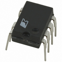
Package / Case
8-DIP (0.300", 7.62mm), 7 Leads
Output Voltage
5.8 V
Input / Supply Voltage (max)
265 VAC
Input / Supply Voltage (min)
85 VAC
Duty Cycle (max)
68 %
Switching Frequency
132 KHz
Supply Current
380 uA
Operating Temperature Range
- 40 C to + 150 C
Mounting Style
Through Hole
Supply Voltage
265VAC
Digital Ic Case Style
DIP
No. Of Pins
8
No. Of Regulated Outputs
1
Filter Terminals
DIP
Rohs Compliant
Yes
On Resistance Rds(on)
5.2ohm
Lead Free Status / RoHS Status
Lead free / RoHS Compliant
Other names
596-1055-5
Available stocks
Company
Part Number
Manufacturer
Quantity
Price

Company:
Part Number:
TNY268PN
Manufacturer:
PowerInt
Quantity:
260 650
Company:
Part Number:
TNY268PN
Manufacturer:
POWER
Quantity:
20 000
Part Number:
TNY268PN
Manufacturer:
POWER
Quantity:
20 000


the appropriate current limit. At high loads, when the EN/UV
pin is high (less than 240 μA out of the pin), a switching cycle
with the full current limit occurs. At lighter loads, when EN/UV
is high, a switching cycle with a reduced current limit occurs.
At near maximum load, TinySwitch-II will conduct during
nearly all of its clock cycles (Figure 6). At slightly lower load, it
will “skip” additional cycles in order to maintain voltage
regulation at the power supply output (Figure 7). At medium
loads, cycles will be skipped and the current limit will be
reduced (Figure 8). At very light loads, the current limit will be
Figure 7.
Figure 6.
www.powerint.com
V
V
I
I
CLOCK
CLOCK
DRAIN
DRAIN
D
DRAIN
D
DRAIN
MAX
MAX
V
V
EN
EN
TinySwitch-II Operation at Moderately Heavy Loading.
TinySwitch-II Operation at Near Maximum Loading.
PI-2667-090700
PI-2749-050301
reduced even further (Figure 9). Only a small percentage of
cycles will occur to satisfy the power consumption of the
power supply.
The response time of the TinySwitch-II ON/OFF control
scheme is very fast compared to normal PWM control. This
provides tight regulation and excellent transient response.
Power Up/Down
The TinySwitch-II requires only a 0.1 μF capacitor on the
BYPASS pin. Because of its small size, the time to charge this
capacitor is kept to an absolute minimum, typically 0.6 ms.
Due to the fast nature of the ON/OFF feedback, there is no
overshoot at the power supply output. When an external
resistor (2 MΩ) is connected from the positive DC input to the
EN/UV pin, the power MOSFET switching will be delayed
during power-up until the DC line voltage exceeds the
threshold (100 V). Figures 10 and 11 show the power-up timing
waveform of TinySwitch-II in applications with and without an
external resistor (2 MΩ) connected to the EN/UV pin.
During power-down, when an external resistor is used, the
power MOSFET will switch for 50 ms after the output loses
regulation. The power MOSFET will then remain off without
any glitches since the undervoltage function prohibits restart
when the line voltage is low.
Figure 12 illustrates a typical power-down timing waveform of
TinySwitch-II. Figure 13 illustrates a very slow power-down
timing waveform of TinySwitch-II as in standby applications.
The external resistor (2 MΩ) is connected to the EN/UV pin in
this case to prevent unwanted restarts.
The TinySwitch-II does not require a bias winding to provide
power to the chip, because it draws the power directly from
the DRAIN pin (see Functional Description above). This has
Figure 8.
V
I
CLOCK
D
DRAIN
DRAIN
MAX
V
EN
TinySwitch-II Operation at Medium Loading.
TNY263-268
PI-2377-091100
Rev. H 02/09
5
Related parts for TNY268PN
Image
Part Number
Description
Manufacturer
Datasheet
Request
R

Part Number:
Description:
SOP-16
Manufacturer:
Power Integrations
Datasheet:
Part Number:
Description:
DIP8
Manufacturer:
Power Integrations
Datasheet:
Part Number:
Description:
TO-263
Manufacturer:
Power Integrations
Datasheet:
Part Number:
Description:
TO-263
Manufacturer:
Power Integrations
Datasheet:
Part Number:
Description:
Manufacturer:
Power Integrations
Datasheet: