DS1251WP-120 Maxim Integrated Products, DS1251WP-120 Datasheet
DS1251WP-120
Specifications of DS1251WP-120


Related parts for DS1251WP-120


DS1251WP-120 Summary of contents
Page 1
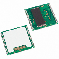
... Replaceable Battery (PowerCap) Pin-for-Pin Compatible with Other Densities of DS124xP Phantom Clocks Underwriters Laboratory (UL) Recognized (www.maxim-ic.com/qa/info/ul/) Available in Lead-Free Package PowerCap is a registered trademark of Maxim Integrated Products, Inc. 4096k NV SRAM with Phantom Clock PIN CONFIGURATIONS TOP VIEW A18/RST A16 A14 A12 ...
Page 2
... PIN-PACKAGE PIN-PACKAGE TOP MARK TOP MARK 32 EMOD (0.740a) DS1251W-120 32 EMOD (0.740a) DS1251W-120+ 32 EMOD (0.740a) DS1251W-12I IND 32 EMOD (0.740a) DS1251W-12I+IND 34 PowerCap* DS1251WP-120 34 PowerCap* DS1251WP-120+ 34 PowerCap* DS1251WP-120IND 34 PowerCap* DS1251WP-120IND+ 32 EMOD (0.740a) DS1251Y-070 32 EMOD (0.740a) DS1251Y-070+ 34 PowerCap* DS1251YP-070 34 PowerCap* DS1251YP-070+ 34 PowerCap* DS1251YP-070 IND 34 PowerCap* ...
Page 3
... V condition occurs, the lithium energy source is automatically switched on and write protection is unconditionally enabled to prevent garbled data in both the memory and real-time clock. The phantom clock provides timekeeping information including hundredths of seconds, seconds, minutes, hours, days, dates, months, and years. The date at the end of the month is automatically adjusted for months with fewer than 31 days, including correction for leap years ...
Page 4
... Data transfer to and from the timekeeping function is accomplished with a serial bit stream under control of chip e ble, output enable, and write enable. Initially, a read cycle to any memory location using the na and control of the phantom clock starts the pattern recognition sequence by moving a pointer to ...
Page 5
... The next 64 cycles will cause the receive or transmit data on DQ0, depending on the level of th locations outside the memory block can be interleaved with re cognition sequence or data transfer sequence to the phantom clock. PHANTOM CLOCK REGISTER INFORMATION The phantom clock information is contained in eight registers of 8 bits, each of which is sequentially accessed 1 bit at a time after the 64-bit pattern recognition sequence has been completed ...
Page 6
PHANTOM CLOCK REGISTER DEFINITION Figure 2 AM/PM/12/24 MODE Bit 7 of the hours register is defined as the 12-hour or 24-hour mode-select bit. When high, the 12-hour mode is selected. In the 12-hour mode, bit 5 is the AM/PM bit ...
Page 7
BATTERY LONGEVITY The DS1251 has a lithium power source that is designed to provide energy for clock activity, and clock and RAM data retention when the V is sufficient to power the DS1251 continuously for the life of the equipment ...
Page 8
ABSOLUTE MAXIMUM RATINGS Voltage Range on Any Pin Relative to Ground……………………………………………..-0.3V to +6.0V Soldering Temperature Range……………………………………..+260°C for 10 seconds (DIP) (Note 13) This is a stress rating only and functional operation of the device at these or any other conditions ...
Page 9
DC ELECTRICAL CHARACTERISTICS (T = Over the operating range.) (5V) A PARAMETER Input Leakage Current I/O Leakage Current CE V ≤ Output Current at 2.4V Output Current at 0.4V Standby Current CE = 2.2V Standby Current ...
Page 10
... MEMORY AC ELECTRICAL CHARACTERISTICS (T = Over the operating range.) (5V) A PARAMETER Read Cycle Time Access Time OE to Output Valid CE to Output Valid Output Active Output High-Z from Deselection Output Hold from Address Change Write Cycle Time Write Pulse Width Address Setup Time Write Recovery Time ...
Page 11
PHANTOM CLOCK AC ELECTRICAL CHARACTERISTICS (T = Over the operating range.) (5V) A PARAMETER Read Cycle Time CE Access Time OE Access Time CE to Output Low Output Low Output High Output High-Z Read ...
Page 12
... MEMORY AC ELECTRICAL CHARACTERISTICS (T = Over the operating range.) (3.3V) A PARAMETER Read Cycle Time Access Time OE to Output Valid CE to Output Valid Output Active Output High-Z from Deselection Output Hold from Address Change Write Cycle Time Write Pulse Width Address Setup Time Write Recovery Time ...
Page 13
POWER-DOWN/POWER-UP TIMING (T = Over the operating range.) (3.3V) A PARAMETER before Power-Down IH V Slew from PF(MAX PF(MIN Slew from PF(MAX) V (CE ...
Page 14
... MEMORY READ CYCLE (Note 1) MEMORY WRITE CYCLE 1 (Notes 2, 6, and ...
Page 15
... MEMORY WRITE CYCLE 2 (Notes 2 and 8) RESET FOR PHANTOM CLOCK READ CYCLE TO PHANTOM CLOCK ...
Page 16
WRITE CYCLE TO PHANTOM CLOCK POWER-DOWN/POWER-UP CONDITION (5V ...
Page 17
POWER-DOWN/POWER-UP CONDITION (3.3V ...
Page 18
AC TEST CONDITIONS Output Load: 50pF + 1TTL Gate Input Pulse Levels Timing Measurement Reference Levels Input: 1.5V Output: 1.5V Input Pulse Rise and Fall Times: 5ns NOTES high for a read cycle. 2) ...
Page 19
PACKAGE INFORMATION For the latest package outline information and land patterns www.maxim-ic.com/packages. PACKAGE TYPE PACKAGE CODE 32 EDIP MDT32+5 34 PWRCP PC2+5 DS1251P DOCUMENT NO. 21-0245 21-0246 PKG DIM MIN A 0.920 B 0.980 C - 0.052 D ...
Page 20
DS1251P WITH DS9034PCX ATTACHED PKG DIM COMPONENTS AND PLACEMENT MAY VARY FROM EACH DEVICE TYPE INCHES MIN NOM MAX 0.920 0.925 0.930 0.955 0.960 0.965 0.240 0.245 0.250 0.052 0.055 ...
Page 21
... Maxim/Dallas Semiconductor cannot assume responsibility for use of any circuitry other than circuitry entirely embodied in a Maxim/Dallas Semiconductor product. No circuit patent licenses are implied. Maxim/Dallas Semiconductor reserves the right to change the circuitry and specifications without notice at any time The Maxim logo is a registered trademark of Maxim Integrated Products, Inc. The Dallas logo is a registered trademark of Dallas Semiconductor Corporation. PKG DIM ...