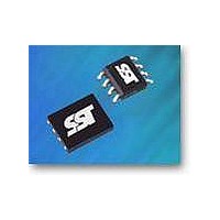
SST25VF016B-50-4I-QAF Microchip Technology, SST25VF016B-50-4I-QAF Datasheet - Page 10

SST25VF016B-50-4I-QAF
Manufacturer Part Number
SST25VF016B-50-4I-QAF
Description
IC FLASH SER 16M 50MHZ SPI 8WSON
Manufacturer
Microchip Technology
Specifications of SST25VF016B-50-4I-QAF
Memory Type
FLASH
Memory Size
16M (2M x 8)
Operating Temperature
-40°C ~ 85°C
Package / Case
8-WSON
Format - Memory
FLASH
Speed
50MHz
Interface
SPI Serial
Voltage - Supply
2.7 V ~ 3.6 V
Architecture
Sectored
Interface Type
4-Wire
Supply Voltage (max)
3.6 V
Supply Voltage (min)
2.7 V
Maximum Operating Current
15 mA
Mounting Style
SMD/SMT
Organization
4 KB x 512
Lead Free Status / RoHS Status
Lead free / RoHS Compliant
Lead Free Status / RoHS Status
Lead free / RoHS Compliant, Lead free / RoHS Compliant
Available stocks
Company
Part Number
Manufacturer
Quantity
Price
Company:
Part Number:
SST25VF016B-50-4I-QAF
Manufacturer:
AD
Quantity:
1 200
A Microchip Technology Company
©2011 Silicon Storage Technology, Inc.
Read (25 MHz)
The Read instruction, 03H, supports up to 25 MHz Read. The device outputs the data starting from the
specified address location. The data output stream is continuous through all addresses until termi-
nated by a low to high transition on CE#. The internal address pointer will automatically increment until
the highest memory address is reached. Once the highest memory address is reached, the address
pointer will automatically increment to the beginning (wrap-around) of the address space. Once the
data from address location 1FFFFFH has been read, the next output will be from address location
000000H.
The Read instruction is initiated by executing an 8-bit command, 03H, followed by address bits [A
A
sequence.
Figure 5: Read Sequence
0
SCK
CE#
]. CE# must remain active low for the duration of the Read cycle. See Figure 5 for the Read
SO
2. Address bits above the most significant bit of each density can be V
3. 4KByte Sector Erase addresses: use A
4. 32KByte Block Erase addresses: use A
5. 64KByte Block Erase addresses: use A
6. To continue programming to the next sequential address location, enter the 8-bit command, ADH, followed by 2 bytes of
7. The Read-Status-Register is continuous with ongoing clock cycles until terminated by a low to high transition on CE#.
8. Manufacturer’s ID is read with A
SI
data to be programmed. Data Byte 0 will be programmed into the initial address [A
programmed into the
initial address [A
turer’s ID and device ID output stream is continuous until terminated by a low-to-high transition on CE#.
MODE 3
MODE 0
MSB
0 1 2 3 4 5 6 7 8
23
-A
03
1
] with A
HIGH IMPEDANCE
0
=1.
0
=0, and Device ID is read with A
MSB
ADD.
MS
MS
MS
-A
15 16
-A
-A
10
12,
15,
16,
ADD.
remaining addresses are don’t care but must be set either at V
remaining addresses are don’t care but must be set either at V
remaining addresses are don’t care but must be set either at V
23 24
ADD.
MSB
31 32
16 Mbit SPI Serial Flash
0
D
=1. All other address bits are 00H. The Manufac-
OUT
IL
N
or V
39 40
IH
.
D
N+1
OUT
47 48
23
-A
D
N+2
1
OUT
] with A
SST25VF016B
55 56
0
D
=0, Data Byte 1 will be
N+3
OUT
S71271-04-000
63 64
D
1271 ReadSeq.0
N+4
Data Sheet
OUT
IL
IL
IL
or V
70
or V
or V
IH.
IH.
IH.
01/11
23
-


