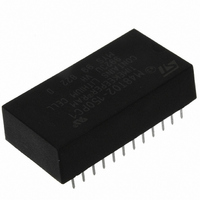
M48Z02-150PC1 STMicroelectronics, M48Z02-150PC1 Datasheet - Page 15

M48Z02-150PC1
Manufacturer Part Number
M48Z02-150PC1
Description
IC NVSRAM 16KBIT 150NS 24DIP
Manufacturer
STMicroelectronics
Datasheets
1.M48Z02-150PC1.pdf
(22 pages)
2.M48Z02-150PC1.pdf
(21 pages)
3.M48Z02-150PC1.pdf
(10 pages)
Specifications of M48Z02-150PC1
Format - Memory
RAM
Memory Type
NVSRAM (Non-Volatile SRAM)
Memory Size
16K (2K x 8)
Speed
150ns
Interface
Parallel
Voltage - Supply
4.75 V ~ 5.5 V
Operating Temperature
0°C ~ 70°C
Package / Case
24-DIP (600 mil) Module
Data Bus Width
8 bit
Organization
2 Kb x 8
Interface Type
Parallel
Access Time
150 ns
Supply Voltage (max)
5.5 V
Supply Voltage (min)
4.75 V
Operating Current
80 mA
Maximum Operating Temperature
70 C
Minimum Operating Temperature
0 C
Mounting Style
Through Hole
Capacitance, Input
10 pF
Capacitance, Output
10 pF
Current, Input, Leakage
±1 μA
Current, Operating
80 mA
Current, Output, Leakage
±1
Data Retention
10 yrs.
Density
16K
Package Type
PCDIP24
Power Dissipation
1 W
Temperature, Operating
0 to +70 °C
Time, Access
150 ns
Time, Fall
≤5 ns
Time, Rise
≤5 ns
Voltage, Input, High
5.05 to 5.8 V
Voltage, Input, Low
0.8 V
Voltage, Output, High
2.4 V
Voltage, Output, Low
0.4 V
Voltage, Supply
4.75 to 5.5 V
Lead Free Status / RoHS Status
Lead free / RoHS Compliant
Other names
497-2865-5
Available stocks
Company
Part Number
Manufacturer
Quantity
Price
Company:
Part Number:
M48Z02-150PC1
Manufacturer:
HI-SIN
Quantity:
3 400
Company:
Part Number:
M48Z02-150PC1
Manufacturer:
STM
Quantity:
5 530
M48Z02, M48Z12
Table 8.
1. Valid for ambient operating temperature: T
2. Outputs deselected.
Figure 10. Power down/up mode AC waveforms
Note:
Symbol
I
I
I
V
LO
V
I
V
CC1
CC2
V
I
CC
OH
OL
LI
IH
IL
(2)
V CC
V PFD (max)
V PFD (min)
V SO
INPUTS
OUTPUTS
Input leakage current
Output leakage current
Supply current
Supply current (standby) TTL
Supply current (standby) CMOS
Input low voltage
Input high voltage
Output low voltage
Output high voltage
DC characteristics
Inputs may or may not be recognized at this time. Caution should be taken to keep E high as
V
rises above V
reset is being applied to the processor, a reset condition may not occur until after the system
is running.
CC
rises past V
tPD
(PER CONTROL INPUT)
Parameter
VALID
RECOGNIZED
PFD
tF
PFD
(min) but before normal system operations begin. Even though a power on
(min). Some systems may perform inadvertent WRITE cycles after V
A
= 0 to 70 °C; V
tFB
Doc ID 2420 Rev 8
CC
Test condition
0V ≤ V
E = V
0V ≤ V
Outputs open
I
I
= 4.75 to 5.5 V or 4.5 to 5.5 V (except where noted).
OL
OH
tDR
E = V
= 2.1 mA
CC
= –1 mA
OUT
IN
– 0.2 V
DON'T CARE
HIGH-Z
≤ V
IH
≤ V
CC
CC
(1)
tRB
–0.3
Min
2.2
2.4
NOTE
DC and AC parameters
tR
(PER CONTROL INPUT)
V
CC
Max
tREC
RECOGNIZED
0.8
0.4
±1
±1
80
3
3
VALID
+ 0.3
AI00606
Unit
mA
mA
mA
µA
µA
V
V
V
V
15/22
CC


