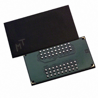
MT48H4M16LFB4-75 IT:H TR Micron Technology Inc, MT48H4M16LFB4-75 IT:H TR Datasheet - Page 9

MT48H4M16LFB4-75 IT:H TR
Manufacturer Part Number
MT48H4M16LFB4-75 IT:H TR
Description
IC SDRAM 64MBIT 133MHZ 54VFBGA
Manufacturer
Micron Technology Inc
Datasheet
1.MT48H4M16LFB4-75_ITH_TR.pdf
(62 pages)
Specifications of MT48H4M16LFB4-75 IT:H TR
Format - Memory
RAM
Memory Type
Mobile SDRAM
Memory Size
64M (4M x 16)
Speed
133MHz
Interface
Parallel
Voltage - Supply
1.7 V ~ 1.9 V
Operating Temperature
-40°C ~ 85°C
Package / Case
54-VFBGA
Lead Free Status / RoHS Status
Lead free / RoHS Compliant
Other names
557-1391-2
Figure 4:
Burst Length (BL)
PDF: 09005aef8237ed98/Source: 09005aef8237ed68
64mb_x16_Mobile SDRAM_Y24L_2.fm - Rev. C 10/07 EN
Mode Register Definition
M13 M12
0
0
0
1
M8
0
–
M9
0
1
Mode Register Definintion
Base mode register
Extended mode register
M7
The mode register must be loaded when all banks are idle, and the controller must wait
t
will result in unspecified operation.
0
–
Read and write accesses to the SDRAM are burst oriented, with the burst length (BL)
being programmable, as shown in Figure 4 on page 9. The BL determines the maximum
number of column locations that can be accessed for a given READ or WRITE command.
BLs of 1, 2, 4, or 8 locations are available for both the sequential and the interleaved
burst types. Reserved states must not be used, as unknown operation or incompatibility
with future versions may result.
When a READ or WRITE command is issued, a block of columns equal to the BL is effec-
tively selected. All accesses for that burst take place within this block, meaning that the
burst will wrap within the block if a boundary is reached. The block is uniquely selected
MRD before initiating the subsequent operation. Violating either of these requirements
Programmed burst length
13
0
M13
BA1 BA0
Single location access
Defined
M6–M0
Write Burst Mode
M12
12
0
–
Reserved
M11
11
A11
Normal operation
All other states reserved
Operating Mode
10
M10
A10
M6
0
0
0
0
1
1
1
1
WB
M5
0
0
1
1
0
0
1
1
M9
A9
9
OP Mode
M4
0
1
0
1
0
1
0
1
M8
A8
8
M7
A7
7
CAS Latency
CAS Latency
9
Reserved
Reserved
Reserved
Reserved
Reserved
Reserved
M6
A6
6
2
3
M5
5
A5
M4
4
Micron Technology, Inc., reserves the right to change products or specifications without notice.
A4
BT
M3
A3
3
64Mb: 4 Meg x 16 Mobile SDRAM
Burst Length
M2
0
0
0
0
1
1
1
1
M2
A2
2
M3
0
1
M1
0
0
1
1
0
0
1
1
M1
A1
1
M0
0
1
0
1
0
1
0
1
Mode Register Definition
M0
A0
0
Reserved
Reserved
Reserved
Reserved
M3 = 0
Burst Type
Interleaved
Sequential
Burst Length
1
2
4
8
Address bus
Mode
register (Mx)
©2006 Micron Technology, Inc. All rights reserved.
Reserved
Reserved
Reserved
Reserved
M3 = 1
1
2
4
8


