74FST3257MNTWG ON Semiconductor, 74FST3257MNTWG Datasheet - Page 4
74FST3257MNTWG
Manufacturer Part Number
74FST3257MNTWG
Description
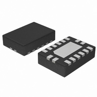
IC MUX/DEMUX QUAD 2:1 16QFN
Manufacturer
ON Semiconductor
Series
74FSTr
Type
Multiplexer/Demultiplexerr
Datasheet
1.74FST3257DR2G.pdf
(8 pages)
Specifications of 74FST3257MNTWG
Circuit
4 x 1:2
Independent Circuits
1
Current - Output High, Low
15mA, 64mA
Voltage Supply Source
Single Supply
Voltage - Supply
4 V ~ 5.5 V
Operating Temperature
-40°C ~ 85°C
Mounting Type
Surface Mount
Package / Case
16-TFQFN Exposed Pad
Lead Free Status / RoHS Status
Lead free / RoHS Compliant
Available stocks
Company
Part Number
Manufacturer
Quantity
Price
Company:

Part Number:
74FST3257MNTWG
Manufacturer:
ON
Quantity:
1 080
Part Number:
74FST3257MNTWG
Manufacturer:
ON/安森美
Quantity:
20 000


*Typical values are at V
6. Measured by the voltage drop between A and B pins at the indicated current through the switch. On resistance is determined by the lower
7. This parameter is guaranteed by design but is not tested. The bus switch contributes no propagation delay other than the RC delay of the
8. T
CAPACITANCE
DC ELECTRICAL CHARACTERISTICS
AC ELECTRICAL CHARACTERISTICS
Symbol
Symbol
Symbol
t
t
DI
of the voltages on the two (A or B) pins.
t
typical On resistance of the switch and the 50 pF load capacitance, when driven by an ideal voltage source (zero output impedance).
R
t
t
t
C
C
PHL
PZH
PHZ
V
V
I
C
V
I
PLH
PZL
PLZ
A
OZ
CC
I
ON
I/O
I/O
IK
IH
CC
IL
I
IN
= )25_C, f = 1 MHz, Capacitance is characterized but not tested.
,
,
,
Clamp Diode Voltage
High−Level Input Voltage
Low−Level Input Voltage
Input Leakage Current
Off−State Leakage Current
Switch On Resistance (Note 6)
Quiescent Supply Current
Increase In I
Prop Delay Bus to Bus (Note 7)
Prop Delay, Select to Bus A
Output Enable Time, Select to Bus B
Output Enable Time, I
Output Disable Time, Select to Bus B
Output Disable Time, I
Control Pin Input Capacitance
A Port Input/Output Capacitance
B Port Input/Output Capacitance
(Note 8)
CC
CC
Parameter
Parameter
Parameter
= 5.0 V and T
per Input
OE
OE
to Bus A, B
to Bus A, B
A
= 25_C.
I
0 v V
0 v A, B v V
V
V
V
V
V
One input at 3.4 V,
Other inputs at V
IN
V
V
V
V
V
V
V
V
IN
IN
IN
IN
IN
I
I
I
I
I
CC
CC
CC
= *18mA
= OPEN
= 7 V for t
= OPEN for t
= 7 V for t
= OPEN for t
= 0 V, I
= 0 V, I
= 2.4 V, I
= 2.4 V, I
= V
, OE = 5.0 V
, OE = 5.0 V
http://onsemi.com
= 5.0 V
IN
CC
v 5.5 V
Conditions
Conditions
or GND, I
IN
IN
IN
IN
PZL
PLZ
= 64 mA
= 30 mA
CC
4
= 15 mA
= 15 mA
CC
PZH
PHZ
or GND
OUT
Conditions
= 0
4.0 to 5.5
4.0 to 5.5
V
V
4.5
5.5
5.5
4.5
4.5
4.5
4.0
5.5
5.5
Min
(V)
1.0
1.0
1.0
1.0
1.0
CC
CC
C
= 4.5−5.5 V
L
= 50 pF, RU = RD = 500 W
T
A
= *40_C to )85_C
Max
0.25
Min
2.0
4.7
5.2
5.1
5.2
5.5
T
A
= *40_C to )85_C
Typ*
Min
Typ
11
4
4
8
V
3
7
5
CC
= 4.0 V
*1.2
$1.0
$1.0
Max
Max
0.25
Max
0.8
2.5
5.2
5.7
5.6
5.5
5.5
15
20
7
7
3
Unit
Unit
Unit
mA
mA
mA
mA
pF
pF
pF
ns
ns
ns
W
V
V
V
Related parts for 74FST3257MNTWG
Image
Part Number
Description
Manufacturer
Datasheet
Request
R

Part Number:
Description:
Quad 2 1 Multiplexer/ Demultiplexer Bus Switch
Manufacturer:
ON Semiconductor
Datasheet:
Part Number:
Description:
ON Semiconductor [VOLTAGE REGULATOR]
Manufacturer:
ON Semiconductor
Datasheet:
Part Number:
Description:
357-036-542-201 CARDEDGE 36POS DL .156 BLK LOPRO
Manufacturer:
ON Semiconductor
Datasheet:
Part Number:
Description:
357-036-542-201 CARDEDGE 36POS DL .156 BLK LOPRO
Manufacturer:
ON Semiconductor
Datasheet:
Part Number:
Description:
357-036-542-201 CARDEDGE 36POS DL .156 BLK LOPRO
Manufacturer:
ON Semiconductor
Datasheet:
Part Number:
Description:
357-036-542-201 CARDEDGE 36POS DL .156 BLK LOPRO
Manufacturer:
ON Semiconductor
Datasheet:
Part Number:
Description:
357-036-542-201 CARDEDGE 36POS DL .156 BLK LOPRO
Manufacturer:
ON Semiconductor
Datasheet:
Part Number:
Description:
357-036-542-201 CARDEDGE 36POS DL .156 BLK LOPRO
Manufacturer:
ON Semiconductor
Datasheet:
Part Number:
Description:
357-036-542-201 CARDEDGE 36POS DL .156 BLK LOPRO
Manufacturer:
ON Semiconductor
Datasheet:
Part Number:
Description:
357-036-542-201 CARDEDGE 36POS DL .156 BLK LOPRO
Manufacturer:
ON Semiconductor
Datasheet:
Part Number:
Description:
357-036-542-201 CARDEDGE 36POS DL .156 BLK LOPRO
Manufacturer:
ON Semiconductor
Datasheet:
Part Number:
Description:
357-036-542-201 CARDEDGE 36POS DL .156 BLK LOPRO
Manufacturer:
ON Semiconductor
Datasheet:
Part Number:
Description:
Manufacturer:
ON Semiconductor
Datasheet:
Part Number:
Description:
Manufacturer:
ON Semiconductor
Datasheet: