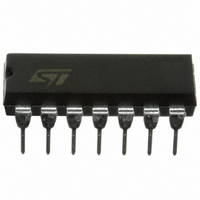
HCF4047BEY STMicroelectronics, HCF4047BEY Datasheet - Page 6

HCF4047BEY
Manufacturer Part Number
HCF4047BEY
Description
IC MULTIVIBRATOR LOW PWR 14-DIP
Manufacturer
STMicroelectronics
Series
4000Br
Specifications of HCF4047BEY
Logic Type
Astable, Monostable
Independent Circuits
1
Schmitt Trigger Input
No
Propagation Delay
125ns
Current - Output High, Low
6.8mA, 6.8mA
Voltage - Supply
3 V ~ 20 V
Operating Temperature
-55°C ~ 125°C
Mounting Type
Through Hole
Package / Case
14-DIP (0.300", 7.62mm)
Elements Per Chip
1
Logic Family
4000B
Input Bias Current (max)
0.02 mA
Propagation Delay Time
1000 ns, 450 ns, 300 ns
High Level Output Current
- 2.4 mA
Low Level Output Current
2.4 mA
Supply Voltage (max)
20 V
Supply Voltage (min)
3 V
Maximum Operating Temperature
+ 125 C
Minimum Operating Temperature
- 55 C
Mounting Style
Through Hole
Operating Supply Voltage
3.3 V, 5 V, 9 V, 12 V
Capacitance, Input
5 pF (Typ.)
Circuit Type
Monolithic Integrated
Current, Input
±10 mA
Current, Input, Leakage
± 1 μA (Max.)
Current, Supply
600 μA
Logic Function
Multivibrator
Number Of Circuits
Triple
Package Type
DIP-14
Power Dissipation
200 mW (Per Package)
Special Features
Astable/Monostable
Temperature, Operating, Maximum
125 °C
Temperature, Operating, Minimum
-55 °C
Temperature, Operating, Range
-55 to +125 °C
Time, Delay, Propagation
200 to 80 ns (Typ.)
Voltage, Supply
3 to 20 V
Lead Free Status / RoHS Status
Contains lead / RoHS non-compliant
Other names
497-1358-5
Available stocks
Company
Part Number
Manufacturer
Quantity
Price
Company:
Part Number:
HCF4047BEY
Manufacturer:
AVAGO
Quantity:
5 000
HCF4047B
DYNAMIC ELECTRICAL CHARACTERISTICS (T
(*) Typical temperature coefficient for all V
APPLICATION INFORMATION
1 - CIRCUIT DESCRIPTION
Astable operation is enabled by a high level on the
ASTABLE input. The period of the square wave at
the Q and Q Outputs in this mode of operation is a
function of the external components employed.
"True" input pulses on the ASTABLE input or
"Complement" pulses on the ASTABLE input
allow the circuit to be used as a gatable
multivibrator. The OSCILLATOR output period will
be half of the Q terminal output in the astable
mode. However, a 50% duty cycle is not
guaranteed at this output. In the monostable
6/12
t
t
Symbol
PLH
THL
t
t
r
, t
W
t
t
PHL
TLH
f
Propagation Delay
Time
Transition Time Osc. Out Q, Q
Input Pulse Width
Input Rise and Fall Time All Inputs
Q or Q Deviation from 50% Duty
Factor
Parameter
Astable, Astable
to Osc. Out
Astable, Astable
to Q, Q
+ or - Trigger to
Q, Q
Retrigger to Q, Q
External Reset
to Q, Q
+ Trigger
- Trigger
Reset
Retrigger
DD
value is 0.3 %/°C.
V
DD
10
15
10
15
10
15
10
15
10
15
10
15
10
15
10
15
10
15
10
15
10
15
5
5
5
5
5
5
5
5
5
5
5
(V)
amb
Test Condition
mode, positive-edge triggering is accomplished by
application of a leading-edge pulse to the
+TRIGGER input and a low level to the -TRIGGER
input. For negative-edge triggering, a trailing-edge
pulse is applied to the -TRIGGER and a high level
is applied to the +TRIGGER. Input pulses may be
of any duration relative to the output pulse. The
multivibrator can be retriggered (on the leading
edge only) by applying a common pulse to both
the RETRIGGER and +TRIGGER inputs. In this
mode the output pulse remains high as long as the
input pulse period is shorter than the period
determined by the RC components. An external
countdown option can be implemented by
= 25°C, C
L
= 50pF, R
L
= 200K , t
Min.
Unlimited
Value (*)
Typ.
200
100
350
175
125
500
225
150
300
150
100
250
100
100
200
100
300
115
80
70
50
40
80
50
50
30
75
0.5
0.5
0.1
r
= t
Max.
1000
400
200
160
700
350
250
450
300
600
300
200
500
200
140
200
100
400
160
100
200
100
600
230
150
80
60
f
0.5
1
1
= 20 ns)
Unit
ns
ns
ns
%
s


