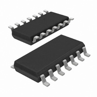
74HCT132D,653 NXP Semiconductors, 74HCT132D,653 Datasheet - Page 5

74HCT132D,653
Manufacturer Part Number
74HCT132D,653
Description
IC TRIGGER NAND QUAD 2-IN 14SOIC
Manufacturer
NXP Semiconductors
Series
74HCTr
Datasheet
1.74HC132N652.pdf
(8 pages)
Specifications of 74HCT132D,653
Number Of Circuits
4
Package / Case
14-SOIC (3.9mm Width), 14-SOL
Logic Type
NAND Gate - Schmitt Trigger
Number Of Inputs
2
Current - Output High, Low
5.2mA, 5.2mA
Voltage - Supply
4.5 V ~ 5.5 V
Operating Temperature
-40°C ~ 125°C
Mounting Type
Surface Mount
Product
NAND
Logic Family
HCT
High Level Output Current
- 4 mA
Low Level Output Current
4 mA
Propagation Delay Time
17 ns
Supply Voltage (max)
5.5 V
Supply Voltage (min)
4.5 V
Maximum Operating Temperature
+ 125 C
Mounting Style
SMD/SMT
Minimum Operating Temperature
- 40 C
Logical Function
NAND
Number Of Elements
4
Operating Supply Voltage (typ)
5V
Operating Temp Range
-40C to 125C
Package Type
SO
Number Of Outputs
1
Technology
CMOS
Mounting
Surface Mount
Pin Count
14
Operating Temperature Classification
Automotive
Quiescent Current
2uA
Operating Supply Voltage (max)
5.5V
Operating Supply Voltage (min)
4.5V
Lead Free Status / RoHS Status
Lead free / RoHS Compliant
Lead Free Status / RoHS Status
Lead free / RoHS Compliant, Lead free / RoHS Compliant
Other names
74HCT132D-T
74HCT132D-T
933714140653
74HCT132D-T
933714140653
Philips Semiconductors
DC CHARACTERISTICS FOR 74HCT
For the DC characteristics see
given below.
Output capability: standard
I
Notes to HCT types
The value of additional quiescent supply current ( I
To determine I
Transfer characteristics for 74HCT
Voltages are referenced to GND (ground = 0 V)
AC CHARACTERISTICS FOR 74HCT
GND = 0 V; t
September 1993
CC
INPUT
nA, nB
SYMBOL PARAMETER
V
V
V
SYMBOL PARAMETER
t
t
PHL
THL
T
T
H
Quad 2-input NAND Schmitt trigger
category: SSI
/ t
/ t
TLH
PLH
positive-going threshold
negative-going threshold 0.5
hysteresis (V
propagation delay
output transition time
r
nA, nB to nY
= t
UNIT LOAD COEFFICIENT
CC
f
= 6 ns; C
0.3
per input, multiply this value by the unit load coefficient shown in the table below.
T
L
= 50 pF
V
“74HC/HCT/HCU/HCMOS Logic Family Specifications”
T
)
min.
min. typ.
1.2
1.4
0.6
0.4
0.4
typ.
20
7
25
1.41
1.59
0.85
0.99
0.56
0.60
25
max. min.
CC
33
15
max. min. max.
1.9
2.1
1.2
1.4
) for a unit load of 1 is given in the family specifications.
T
74HCT
amb
T
5
40 to 85
1.2
1.4
0.5
0.6
0.4
0.4
74HCT
amb
( C)
40 to 85
( C)
max.
41
19
1.9
2.1
1.2
1.4
min.
40 to 125
min. max.
1.2
1.4
0.5
0.6
0.4
0.4
40 to 125
max.
2.1
1.4
1.9
1.2
50
22
. Transfer characteristics are
ns
ns
UNIT
V
V
V
UNIT
74HC/HCT132
V
(V)
4.5
4.5
TEST CONDITIONS
CC
TEST CONDITIONS
V
4.5
5.5
4.5
5.5
4.5
5.5
Product specification
(V)
CC
Fig.13
Fig.13
WAVEFORMS
WAVEFORMS
Figs 6 and 7
Figs 6 and 7
Figs 6 and 7


