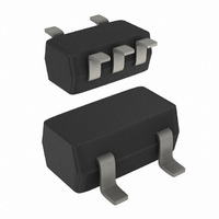
74HCT1G14GW,125 NXP Semiconductors, 74HCT1G14GW,125 Datasheet - Page 9

74HCT1G14GW,125
Manufacturer Part Number
74HCT1G14GW,125
Description
IC INV SCHMITT TRIGGER SOT353
Manufacturer
NXP Semiconductors
Series
74HCTr
Datasheet
1.74HC1G14GW125.pdf
(14 pages)
Specifications of 74HCT1G14GW,125
Number Of Circuits
1
Logic Type
Inverter with Schmitt Trigger
Package / Case
SC-70-5, SC-88A, SOT-323-5, SOT-353, 5-TSSOP
Number Of Inputs
1
Current - Output High, Low
2mA, 2mA
Voltage - Supply
4.5 V ~ 5.5 V
Operating Temperature
-40°C ~ 125°C
Mounting Type
Surface Mount
Logic Family
74HCT
High Level Output Current
- 2 mA
Low Level Output Current
2 mA
Supply Voltage (max)
5.5 V
Supply Voltage (min)
4.5 V
Maximum Operating Temperature
+ 125 C
Minimum Operating Temperature
- 40 C
Mounting Style
SMD/SMT
Operating Supply Voltage
5 V
Logical Function
Inverter Schmit Trig
Number Of Elements
1
Input Type
Schmitt Trigger
Propagation Delay Time
51ns
Operating Supply Voltage (typ)
5V
Package Type
TSSOP
Operating Temp Range
-40C to 125C
Pin Count
5
Quiescent Current
20uA
Output Type
Schmitt Trigger
Technology
CMOS
Mounting
Surface Mount
Operating Temperature Classification
Automotive
Operating Supply Voltage (max)
5.5V
Operating Supply Voltage (min)
4.5V
Lead Free Status / RoHS Status
Lead free / RoHS Compliant
Lead Free Status / RoHS Status
Lead free / RoHS Compliant, Lead free / RoHS Compliant
Other names
74HCT1G14GW-G
74HCT1G14GW-G
935245720125
74HCT1G14GW-G
935245720125
NXP Semiconductors
74HC_HCT1G14_4
Product data sheet
Fig 14. I
Fig 16. Relaxation oscillator using 74HC1G14 and 74HCT1G14
I
CC(AV)
( A)
200
150
100
50
0
V
For 74HC1G14:
For 74HCT1G14:
0
I
CC(AV)
between 0.1
for 74HC1G14 devices; linear change of
2.0
f
74HC1G14 and 74HCT1G14 used in relaxation oscillator circuit, see
Remark: All values given are typical unless otherwise specified.
f
I
=
t
CC(AV)
V
f
=
I
CC
= fall time (ns); 90 % to 10 %
-- -
T
CC(AV)
1
---
T
1
to 0.9
--------------------- -
0.8
differs with positive or negative input transitions, as shown in
------------------------ -
0.67
4.0
= average additional supply current ( A)
1
positive-going
negative-going
RC
1
V
edge
RC
edge
V
CC
CC
(V)
mna036
6.0
Rev. 04 — 17 July 2007
C
R
Fig 15. I
mna035
I
CC(AV)
( A)
74HC1G14; 74HCT1G14
200
150
100
50
0
of V
0
CC(AV)
I
between 0.1
for 74HCT1G14 devices; linear change
2
V
CC
Inverting Schmitt trigger
to 0.9
positive-going
4
negative-going
edge
Figure
Figure 14
V
© NXP B.V. 2007. All rights reserved.
edge
CC
V
CC
(V)
mna058
16.
6
and 15.
9 of 14


