74AUP1G04DTR STMicroelectronics, 74AUP1G04DTR Datasheet
74AUP1G04DTR
Specifications of 74AUP1G04DTR


Related parts for 74AUP1G04DTR


74AUP1G04DTR Summary of contents
Page 1
Features ■ High speed 4.3 ns (max ■ Power down protection on inputs and outputs ■ Balanced propagation delays: ≈ PLH PHL ■ Operating voltage range: V (opr) = 1.2 to 3.6 V ...
Page 2
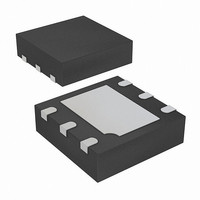
Pin settings 1 Pin settings 1.1 Pin connection Figure 1. Pin connection (top through view GND 1.2 Pin description Table 2. Pin assignment DFN pin SOT pin number number 2/ ...
Page 3
Truth table Figure 2. Truth table Table 3. Truth table Figure 3. Input and output equivalent circuit Input ESD protection GND GND GND Pin settings Overvoltage control Output ...
Page 4
... These are stress ratings only and operation of the device at these or any other conditions above those indicated in the operating sections of this specification is not implied. Exposure to absolute maximum rating conditions for extended periods may affect device reliability. Refer also to the STMicroelectronics SURE Program and other relevant quality documents. Table 4. ...
Page 5
Electrical characteristics Table 6. DC specifications Symbol Parameter 1.2 to 1.95 High level input V 2.0 to 2.7 IH voltage 2.75 to 3.6 1.2 to 1.95 Low level input V 2.0 to 2.7 IL voltage 2.75 to 3.6 ...
Page 6
Electrical characteristics Table 7. AC electrical characteristics Symbol Parameter Propagation t t PLH, PHL delay time Table 8. Capacitive characteristics Symbol Parameter C Input capacitance I C Output capacitance O C Power dissipation capacitance PD 6/18 Test condition V CC ...
Page 7
Test circuit Figure 4. Test circuit generator Table 9. Test setting PLH PHL Table 10. Symbol and values for test circuit and waveform Symbol 1.2 ± 0 10, 15 ...
Page 8
Test circuit Figure 5. Waveform: propagation delay ( MHz; 50% duty cycle 8/ 90 10% t PLH 74AUP1G04 V IH GND t PHL V ...
Page 9
Package mechanical data In order to meet environmental requirements, ST offers these devices in ECOPACK packages. These packages have a Lead-free second level interconnect. The category of second Level Interconnect is marked on the package and on the ...
Page 10
Package mechanical data Table 11. DFN6L (1 mm) package mechanical data Symbol Figure 7. DFN6L (1 mm) package footprint 10/18 Millimeters Typ Min 0.50 0.45 0.02 0 ...
Page 11
Figure 8. SOT-665 (1.6 x 1.6 mm) package outline bp Table 12. SOT665 (1.6 x 1.6 mm) mechanical data Symbol Millimeters Typ Min 0.50 ...
Page 12
Package mechanical data Figure 9. SOT-665 (1.6 x 1.6 mm) package footprint Figure 10. DFN6L (1 mm) carrier tape information 12/18 74AUP1G04 7875978 ...
Page 13
Figure 11. DFN6L (1 mm) reel information drawing (back view) Package mechanical data 13/18 ...
Page 14
Package mechanical data Figure 12. DFN6L (1 mm) reel information drawing (front view) 14/18 74AUP1G04 ...
Page 15
Figure 13. SOT-665 (1.6 x 1.6 mm) carrier tape information Figure 14. SOT-665 (1.6 x 1.6 mm) reel information Package mechanical data 15/18 ...
Page 16
Package mechanical data Table 13. SOT-665 (1.6 x 1.6 mm) reel description (1) Value R1 Min 12.8 Typ 13 Max 13.2 1. Millimeters. 16/18 eint R2 R3 (at hub) 175 59.5 8.4 180 60 8.4 185 60.5 10 74AUP1G04 e1 ...
Page 17
Revision history Table 14. Document revision history Date 28-Mar-2008 Revision 1 Initial release. Revision history Changes 17/18 ...
Page 18
... Information in this document is provided solely in connection with ST products. STMicroelectronics NV and its subsidiaries (“ST”) reserve the right to make changes, corrections, modifications or improvements, to this document, and the products and services described herein at any time, without notice. All ST products are sold pursuant to ST’s terms and conditions of sale. ...