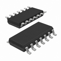
74HCT03D,653 NXP Semiconductors, 74HCT03D,653 Datasheet - Page 8

74HCT03D,653
Manufacturer Part Number
74HCT03D,653
Description
IC QUAD 2-IN NAND GATE 14SOIC
Manufacturer
NXP Semiconductors
Series
74HCTr
Datasheet
1.74HCT03D653.pdf
(8 pages)
Specifications of 74HCT03D,653
Number Of Circuits
4
Package / Case
14-SOIC (3.9mm Width), 14-SOL
Logic Type
NAND Gate
Number Of Inputs
2
Current - Output High, Low
4mA, 4mA
Voltage - Supply
4.5 V ~ 5.5 V
Operating Temperature
-40°C ~ 125°C
Mounting Type
Surface Mount
Product
NAND
Logic Family
HCT
High Level Output Current
- 4 mA
Low Level Output Current
4 mA
Propagation Delay Time
10 ns
Supply Voltage (max)
5.5 V
Supply Voltage (min)
4.5 V
Maximum Operating Temperature
+ 125 C
Mounting Style
SMD/SMT
Minimum Operating Temperature
- 40 C
Lead Free Status / RoHS Status
Lead free / RoHS Compliant
Lead Free Status / RoHS Status
Lead free / RoHS Compliant, Lead free / RoHS Compliant
Other names
568-4575-2
74HCT03D-T
74HCT03D-T
933748640653
74HCT03D-T
74HCT03D-T
933748640653
Philips Semiconductors
APPLICATION INFORMATION
Notes to Figs 9 and 10
If V
protection), this will not affect the receiver provided the current does not exceed 20 mA. At V
guaranteed; R
Note to Application information
All values given are typical unless otherwise specified.
PACKAGE OUTLINES
See
December 1990
Quad 2-input NAND gate
(1) V
(2) V
(3) V
(4) V
P
“74HC/HCT/HCU/HCMOS Logic Package Outlines”
V
CC
CC
CC
CC
CC
(R) = 2.0 V; V
(R) = 5.0 V; V
(R) = 4.5 V; V
(R) = 6.0 V; V
(R)
ON(max)
0.5 V a positive current will flow into the receiver (as described in the “USER GUIDE ”; input/output
IL
IL
IL
IL
can be estimated using Figs 33 and 34 in the “USER GUIDE” .
= 0.5 V.
= 0.8 V.
= 1.35 V.
= 1.8 V.
Fig.10 Minimum resistive load as a function of the pull-up voltage.
(a)
Fig.9 Pull-up configuration.
.
8
(1) R
ON(max)
= 0.26 V / 4 mA = 65
(b)
CC
74HC/HCT03
4.5 V, R
Product specification
(at 25 C)
ON (max)
is not


