NBSG53ABA ON Semiconductor, NBSG53ABA Datasheet - Page 10
NBSG53ABA
Manufacturer Part Number
NBSG53ABA
Description
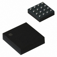
IC FLIP FLOP DIFF CLOCK 16FCBGA
Manufacturer
ON Semiconductor
Type
D-Type Busr
Datasheet
1.NBSG53ABA.pdf
(18 pages)
Specifications of NBSG53ABA
Function
Reset
Output Type
Differential
Number Of Elements
1
Number Of Bits Per Element
2
Frequency - Clock
8GHz
Trigger Type
Positive, Negative
Voltage - Supply
2.375 V ~ 3.465 V
Operating Temperature
-40°C ~ 85°C
Mounting Type
Surface Mount
Package / Case
16-FCBGA
Lead Free Status / RoHS Status
Contains lead / RoHS non-compliant
Current - Output High, Low
-
Delay Time - Propagation
-
Other names
NBSG53ABAOS
Available stocks
Company
Part Number
Manufacturer
Quantity
Price

Company:
Part Number:
NBSG53ABAHTBG
Manufacturer:
ON Semiconductor
Quantity:
10 000
Company:
Part Number:
NBSG53ABAR2
Manufacturer:
ON Semiconductor
Quantity:
10 000


31. Measured using a 500 mV source, 50% duty cycle clock source. Repetitive 1010 input data pattern. All outputs loaded with 50 W to
32. See Figure 14. t
33. V
34. See Figure 10. Duty Cycle % vs. Frequency.
35. For all OLS Configuration.
**When an output level of 400 mV is desired and V
***The device packaged in FCBGA-16 have maximum ambient temperature specification of 70 C and devices packaged in QFN-16 have
Table 11. AC CHARACTERISTICS for QFN-16
V
Symbol
maximum ambient temperature specification of 85 C.
f
t
t
t
t
V
t
t
t
t
t
max
PLH
PHL
SKEW
JITTER
r
f
s
h
rr
CC
INPP
V
CC
INPP
,
= 0 V; V
- 2.0 V. Input edge rates is 40 ps (20% - 80%).
(MAX) cannot exceed V
Maximum Frequency
(See Figures 4, 6, 8, 10, and 11)
(See Figures 5, 7, 9, 10, and 11)
(Note 31)
Propagation Delay to Output Differential
Duty Cycle Skew (Notes 32 and 34) DFF
RMS Random Clock Jitter
(See Figures 4 and 6) (Note 31)
Peak-to-Peak Data Dependent Jitter
Input Voltage Swing/Sensitivity
(Differential Configuration) (Note 33)
Output Rise/Fall Times (20% - 80%)
@ 1 GHz
Setup Time
Hold Time
Reset Recovery
(Note 35)
EE
= -3.465 V to -2.375 V or V
(OLS = V
SKEW
Characteristic
= |t
CC
PLH
- 0.8 V, OLS = FLOAT)
- t
(OLS = V
CC
PHL
- V
| for a nominal 50% differential clock input waveform.
R Q, Q D
**(OLS = V
EE
(OLS = V
f
CLK Q, Q
in
SEL Q, Q
f
CC
DFF, DIV/2
in
(Applicable only when V
v 8 GHz
= 8 Gb/s
D CLK
D CLK
CC
- 0.4 V)
DIV/2
Q, Q
= 2.375 V to 3.465 V; V
DFF
DFF
IN
CC
EE
CC
/2
)
)
- V
Min
150
160
215
195
EE
75
28
15
25
20
30
25
40
http://onsemi.com
> 3.0 V, a 2 kW resistor should be connected from OLS to V
NBSG53A
-40 C
TBD
Typ
215
190
280
270
0.5
10
40
40
35
35
14
12
8
5
9
CC
10
- V
EE
2600
EE
Max
285
280
375
345
20
65
65
65
65
= 0 V
1
< 2600 mV).
Min
150
160
215
195
75
28
15
25
20
30
25
40
25 C
TBD
Typ
215
190
280
270
0.5
10
40
40
35
35
10
12
8
5
7
2600
Max
285
280
375
345
20
65
65
65
65
1
Min
150
160
215
195
75
28
15
25
20
30
25
40
85 C
TBD
Typ
215
190
280
270
0.5
10
40
40
35
35
13
10
8
5
0
EE
.
2600
Max
285
280
375
345
20
65
65
65
65
1
Unit
GHz
mV
ps
ps
ps
ps
ps
ps
ps
Related parts for NBSG53ABA
Image
Part Number
Description
Manufacturer
Datasheet
Request
R

Part Number:
Description:
ON Semiconductor [VOLTAGE REGULATOR]
Manufacturer:
ON Semiconductor
Datasheet:
Part Number:
Description:
357-036-542-201 CARDEDGE 36POS DL .156 BLK LOPRO
Manufacturer:
ON Semiconductor
Datasheet:
Part Number:
Description:
357-036-542-201 CARDEDGE 36POS DL .156 BLK LOPRO
Manufacturer:
ON Semiconductor
Datasheet:
Part Number:
Description:
357-036-542-201 CARDEDGE 36POS DL .156 BLK LOPRO
Manufacturer:
ON Semiconductor
Datasheet:
Part Number:
Description:
357-036-542-201 CARDEDGE 36POS DL .156 BLK LOPRO
Manufacturer:
ON Semiconductor
Datasheet:
Part Number:
Description:
357-036-542-201 CARDEDGE 36POS DL .156 BLK LOPRO
Manufacturer:
ON Semiconductor
Datasheet:
Part Number:
Description:
357-036-542-201 CARDEDGE 36POS DL .156 BLK LOPRO
Manufacturer:
ON Semiconductor
Datasheet:
Part Number:
Description:
357-036-542-201 CARDEDGE 36POS DL .156 BLK LOPRO
Manufacturer:
ON Semiconductor
Datasheet:
Part Number:
Description:
357-036-542-201 CARDEDGE 36POS DL .156 BLK LOPRO
Manufacturer:
ON Semiconductor
Datasheet:
Part Number:
Description:
357-036-542-201 CARDEDGE 36POS DL .156 BLK LOPRO
Manufacturer:
ON Semiconductor
Datasheet:
Part Number:
Description:
357-036-542-201 CARDEDGE 36POS DL .156 BLK LOPRO
Manufacturer:
ON Semiconductor
Datasheet:
Part Number:
Description:
Manufacturer:
ON Semiconductor
Datasheet:
Part Number:
Description:
Manufacturer:
ON Semiconductor
Datasheet:
Part Number:
Description:
Manufacturer:
ON Semiconductor
Datasheet: