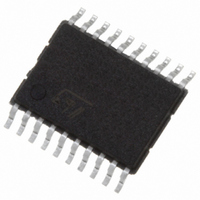
74VHCT574ATTR STMicroelectronics, 74VHCT574ATTR Datasheet - Page 5

74VHCT574ATTR
Manufacturer Part Number
74VHCT574ATTR
Description
IC FLIP FLOP OCT D 3ST 20-TSSOP
Manufacturer
STMicroelectronics
Series
74VHCTr
Type
D-Type Busr
Datasheet
1.74VHCT574ATTR.pdf
(13 pages)
Specifications of 74VHCT574ATTR
Function
Standard
Output Type
Tri-State Non Inverted
Number Of Elements
1
Number Of Bits Per Element
8
Frequency - Clock
130MHz
Delay Time - Propagation
7ns
Trigger Type
Positive Edge
Current - Output High, Low
8mA, 8mA
Voltage - Supply
4.5 V ~ 5.5 V
Operating Temperature
-55°C ~ 125°C
Mounting Type
Surface Mount
Package / Case
20-TSSOP
Lead Free Status / RoHS Status
Lead free / RoHS Compliant
Table 8: Capacitive Characteristics
1) C
load. (Refer to Test Circuit). Average operating current can be obtained by the following equation. I
Flip-Flop)
Table 9: Dynamic Switching Characteristics
1) Worst case package.
2) Max number of outputs defined as (n). Data inputs are driven 0V to 3.0V, (n-1) outputs switching and one output at GND.
3) Max number of data inputs (n) switching. (n-1) switching 0V to 3.0V. Inputs under test switching: 3.0V to threshold (V
(V
Symbol
Symbol
IHD
C
V
V
V
V
C
PD
C
OUT
OLP
OLV
IHD
), f=1MHz.
ILD
PD
IN
is defined as the value of the IC’s internal equivalent capacitance which is calculated from the operating current consumption without
Input Capacitance
Output
Capacitance
Power Dissipation
Capacitance
(note 1)
Dynamic Low
Voltage Quiet
Output (note 1, 2)
Dynamic High
Voltage Input
(note 1, 3)
Dynamic Low
Voltage Input
(note 1, 3)
Parameter
Parameter
V
5.0
5.0
5.0
(V)
CC
Test Condition
Test Condition
C
L
= 50 pF
Min.
Min.
-1.6
3.5
T
T
A
A
Typ.
Typ.
= 25°C
= 25°C
-1.2
1.2
25
4
9
Max.
Max.
1.6
1.5
10
Value
Value
-40 to 85°C
Min.
-40 to 85°C
Min.
CC(opr)
= C
Max.
Max.
10
PD
x V
-55 to 125°C
-55 to 125°C
Min.
Min.
CC
74VHCT574A
ILD
x f
), 0V to threshold
IN
Max.
Max.
+ I
10
CC
/8 (per
Unit
Unit
pF
pF
pF
V
5/13


