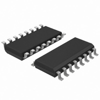
HEF4585BT,652 NXP Semiconductors, HEF4585BT,652 Datasheet - Page 7

HEF4585BT,652
Manufacturer Part Number
HEF4585BT,652
Description
IC COMPARATOR MAGNITUDE 16SOIC
Manufacturer
NXP Semiconductors
Series
4000Br
Type
Magnitude Comparatorr
Specifications of HEF4585BT,652
Package / Case
16-SOIC (3.9mm Width)
Number Of Bits
4
Delay Time - Propagation
45ns
Voltage - Supply
4.5 V ~ 15.5 V
Product
Digital Comparators
Input Bias Current (max)
0.08 mA
Supply Voltage (max)
15.5 V
Supply Voltage (min)
4.5 V
Maximum Operating Temperature
+ 85 C
Mounting Style
SMD/SMT
High Level Output Current
- 3.6 mA
Low Level Output Current
3.6 mA
Minimum Operating Temperature
- 40 C
Propagation Delay Time
320 ns, 130 ns, 90 ns
Logic Family
4000
Technology
CMOS
Output Function
A<B, A=B, A>B
Package Type
SO
Quiescent Current
80uA
Mounting
Surface Mount
Pin Count
16
Polarity
Non-Inverting
Abs. Propagation Delay Time
320ns
Operating Supply Voltage (typ)
3.3/5/9/12V
Operating Supply Voltage (max)
15V
Operating Supply Voltage (min)
3V
Operating Temperature (max)
85C
Operating Temperature (min)
-40C
Operating Temperature Classification
Industrial
Lead Free Status / RoHS Status
Lead free / RoHS Compliant
Current - Supply
-
Operating Temperature
-
Lead Free Status / Rohs Status
Compliant
Other names
933373340652
HEF4585BTD
HEF4585BTD
HEF4585BTD
HEF4585BTD
NXP Semiconductors
11. Dynamic characteristics
Table 7.
V
[1]
[2]
[3]
Table 8.
P
HEF4585B_5
Product data sheet
Symbol
t
t
t
Symbol Parameter
P
PHL
PLH
t
SS
D
D
can be calculated from the formulas shown. V
= 0 V; T
The typical values of the propagation delay and transition times are calculated from the extrapolation formulas shown (C
Qn is QA>B, QA<B or QA=B
In is IA>B, IA<B or IA=B
dynamic power dissipation
Parameter
HIGH to LOW
propagation delay
LOW to HIGH
propagation delay
transition time
Dynamic characteristics
Dynamic power dissipation P
amb
= 25
°
C; for test circuit see
Conditions
An, Bn to Qn;
see
In to Qn;
see
An, Bn to Qn;
see
In to Qn;
see
see
Figure 4
Figure 4
Figure 4
Figure 4
Figure 4
V
10 V
15 V
5 V
DD
Figure 5
D
[1][2]
Typical formula for P
P
P
P
D
D
D
Rev. 05 — 22 December 2009
SS
= 1250 × f
= 5500 × f
= 15000 × f
V
10 V
15 V
10 V
15 V
10 V
15 V
10 V
15 V
10 V
15 V
= 0 V; C
unless otherwise specified.
5 V
5 V
5 V
5 V
5 V
DD
i
i
L
+ Σ(f
+ Σ(f
i
= 50 pF; t
+ Σ(f
Extrapolation formula
133 ns + (0.55 ns/pF)C
123 ns + (0.55 ns/pF)C
54 ns + (0.23 ns/pF)C
37 ns + (0.16 ns/pF)C
83 ns + (0.55 ns/pF)C
34 ns + (0.23 ns/pF)C
22 ns + (0.16 ns/pF)C
49 ns + (0.23 ns/pF)C
37 ns + (0.16 ns/pF)C
93 ns + (0.55 ns/pF)C
39 ns + (0.23 ns/pF)C
27 ns + (0.16 ns/pF)C
10 ns + (1.00 ns/pF)C
9 ns + (0.42 ns/pF)C
6 ns + (0.28 ns/pF)C
o
o
o
× C
× C
× C
D
(μW)
L
L
r
) × V
) × V
L
= t
) × V
f
≤
DD
DD
DD
20 ns; T
2
2
2
where:
f
f
C
V
Σ(f
i
o
L
L
L
L
L
L
L
L
L
L
L
L
L
L
L
[3]
amb
DD
= input frequency in MHz,
L
= output frequency in MHz,
o
= output load capacitance in pF,
× C
= supply voltage in V,
= 25
4-bit magnitude comparator
L
Min
-
-
-
-
-
-
-
-
-
-
-
-
-
-
-
) = sum of the outputs.
°
C.
HEF4585B
Typ
160
110
150
120
65
45
45
30
60
45
50
35
60
30
20
© NXP B.V. 2009. All rights reserved.
Max
320
130
220
300
120
240
100
120
90
90
60
90
70
60
40
L
in pF).
Unit
ns
ns
ns
ns
ns
ns
ns
ns
ns
ns
ns
ns
ns
ns
ns
7 of 15


