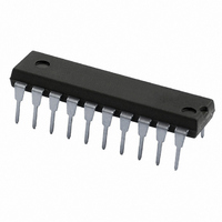
74ABT2241N,112 NXP Semiconductors, 74ABT2241N,112 Datasheet - Page 5

74ABT2241N,112
Manufacturer Part Number
74ABT2241N,112
Description
IC BUFF/DVR TRI-ST DUAL 20DIP
Manufacturer
NXP Semiconductors
Series
74ABTr
Datasheet
1.74ABT2241D112.pdf
(12 pages)
Specifications of 74ABT2241N,112
Logic Type
Buffer/Line Driver, Non-Inverting
Number Of Elements
2
Number Of Bits Per Element
4
Current - Output High, Low
32mA, 12mA
Voltage - Supply
4.5 V ~ 5.5 V
Operating Temperature
-40°C ~ 85°C
Mounting Type
Through Hole
Package / Case
20-DIP (0.300", 7.62mm)
Lead Free Status / RoHS Status
Lead free / RoHS Compliant
Other names
74ABT2241N
74ABT2241N
935220730112
74ABT2241N
935220730112
1. Not more than one output should be tested at a time, and the duration of the test should not exceed one second.
2. This is the increase in supply current for each input at 3.4V.
3. This parameter is valid for any V
Philips Semiconductors
AC CHARACTERISTICS
GND = 0V; t
AC WAVEFORMS
V
1996 Sep 30
M
SYMBOL
Octal buffer with 30W series termination resistors
(3-State)
transition time of up to 100 sec is permitted.
Yn OUTPUT
= 1.5V, V
t
t
t
t
An INPUT
t
t
PLH
PHL
PZH
PHZ
PZL
PLZ
Waveform 1. Waveforms Showing the Input (An)
R
IN
= t
Propagation delay
An to Yn
Output enable time
to High and Low level
Output disable time
from High and Low level
= GND to 3.0V
to Output (Yn) Propagation Delays
F
= 2.5ns; C
V
M
t
PLH
PARAMETER
L
V
= 50pF, R
M
CC
between 0V and 2.1V with a transition time of up to 10msec. For V
L
= 500
V
M
t
PHL
WAVEFORM
V
M
SA00028
1
2
2
5
Min
1.0
1.0
1.1
2.1
1.7
1.7
OE INPUT
OE INPUT
Yn OUTPUT
Yn OUTPUT
Waveform 2. Waveforms Showing the 3–State Output
T
V
amb
CC
Typ
= +5.0V
2.7
3.9
3.3
5.4
3.8
3.4
= +25 C
V
M
t
t
PZL
PZH
Enable and Disable Times
Max
4.3
5.3
4.8
7.6
5.6
5.8
LIMITS
V
V
M
M
CC
T
amb
V
= 2.1V to V
Min
1.0
1.0
1.1
2.1
1.7
1.7
CC
= –40 C to +85 C
= +5.0V 0.5V
V
M
t
t
PLZ
PHZ
CC
74ABT2241
Max
= 5V " 10%, a
4.7
5.6
5.8
8.4
6.6
6.4
Product specification
3.5V
V
V
V
V
OL
OL
OH
OH
UNIT
SA00041
ns
ns
ns
+ 0.3V
– 0.3V
0V


