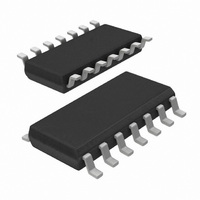
74HC7014D,112 NXP Semiconductors, 74HC7014D,112 Datasheet - Page 5

74HC7014D,112
Manufacturer Part Number
74HC7014D,112
Description
IC BUFF/DVR SCHM TRG 6BIT 14SOIC
Manufacturer
NXP Semiconductors
Series
74HCr
Datasheet
1.74HC7014N112.pdf
(9 pages)
Specifications of 74HC7014D,112
Logic Type
Schmitt Trigger - Buffer, Driver
Package / Case
14-SOIC (3.9mm Width), 14-SOL
Number Of Elements
6
Number Of Bits Per Element
1
Current - Output High, Low
5.2mA, 5.2mA
Voltage - Supply
2 V ~ 6 V
Operating Temperature
-40°C ~ 125°C
Mounting Type
Surface Mount
Logic Family
74HC
Number Of Channels Per Chip
6
Polarity
Non-Inverting
Supply Voltage (max)
6 V
Supply Voltage (min)
2 V
Maximum Operating Temperature
125 C
Mounting Style
SMD/SMT
High Level Output Current
- 5.2 mA
Input Bias Current (max)
2 uA
Low Level Output Current
5.2 mA
Maximum Power Dissipation
500 mW
Minimum Operating Temperature
- 40 C
Propagation Delay Time
175 ns
Number Of Lines (input / Output)
6 / 6
Logical Function
Schmit Trig Buffer
Number Of Elements
6
Number Of Channels
6
Number Of Inputs
6
Number Of Outputs
6
Operating Supply Voltage (typ)
5V
Package Type
SO
Operating Supply Voltage (max)
6V
Operating Supply Voltage (min)
2V
Quiescent Current
2uA
Technology
CMOS
Pin Count
14
Mounting
Surface Mount
Operating Temp Range
-40C to 125C
Operating Temperature Classification
Automotive
Lead Free Status / RoHS Status
Lead free / RoHS Compliant
Lead Free Status / RoHS Status
Lead free / RoHS Compliant, Lead free / RoHS Compliant
Other names
568-1488-5
74HC7014D
935059840112
74HC7014D
935059840112
Philips Semiconductors
AC CHARACTERISTICS FOR 74HC
GND = 0 V; t
TRANSFER CHARACTERISTIC WAVEFORMS
AC WAVEFORMS
1998 Jul 08
SYMBOL PARAMETER
t
t
t
PHL
PLH
THL
(1)
Hex non-inverting precision Schmitt-trigger
/t
V
TLH
M
Fig.8 Waveforms showing the input (nA) to output (nY) propagation delay and the output transition times.
= 50%; V
propagation
delay
nA, nB to nY
propagation
delay
nA, nB to nY
output transition
time
r
= t
Fig.6 Transfer characteristic.
I
f
= GND to V
= 6 ns; C
CC
L
.
= 50 pF
MIN.
95
38
27
47
23
18
12
7
6
TYP.
+25
475
115
73
175
52
46
20
15
13
MAX.
T
amb
MIN.
40 to +85
( C)
5
600
145
93
220
65
58
25
19
16
MAX.
Fig.7
MIN.
40 to +125
Waveforms showing the definition of
V
715
175
112
260
78
70
30
22
19
T+
MAX.
, V
T
and V
UNIT
ns
ns
ns
H
.
3.00
4.75
6.00
3.00
4.75
6.00
3.00
4.75
6.00
V
(V)
CC
TEST CONDITIONS
Product specification
Fig.8
Fig.8
Fig.8
74HC7014
WAVEFORMS


