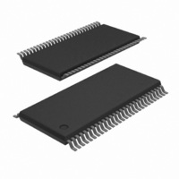
74ALVCH16952DGG,11 NXP Semiconductors, 74ALVCH16952DGG,11 Datasheet

74ALVCH16952DGG,11
Specifications of 74ALVCH16952DGG,11
74ALVCH16952DG-T
935262801118
Related parts for 74ALVCH16952DGG,11
74ALVCH16952DGG,11 Summary of contents
Page 1
Rev. 02 — 27 April 2006 1. General description The 74ALVCH16952 consists of two sections, each containing a dual octal non-inverting registered transceiver. Two 8-bit back to back registers store data flowing in both directions ...
Page 2
Philips Semiconductors 4. Ordering information Table 2. Ordering information Type number Package Temperature range Name DGG + Functional diagram Fig 1. Logic symbol 74ALVCH16952_2 Product data sheet Description TSSOP56 plastic thin shrink small outline package; ...
Page 3
Philips Semiconductors Fig 2. IEC logic symbol Fig 3. Bus hold circuit 74ALVCH16952_2 Product data sheet 16-bit registered transceiver; 3-state 56 1EN3 1OEBA 54 1CEBA G1 55 1CPBA 1C5 1 1OEAB EN4 3 1CEAB G2 2 2C6 1CPAB 29 EN9 ...
Page 4
Philips Semiconductors Fig 4. Schematic diagram (one section) 74ALVCH16952_2 Product data sheet CEAB CPAB OEAB CEBA CPBA OEBA IDENTICAL CHANNELS TO 7 OTHER CHANNELS Rev. 02 — 27 April 2006 74ALVCH16952 16-bit registered transceiver; 3-state ...
Page 5
Philips Semiconductors 6. Pinning information 6.1 Pinning Fig 5. Pin configuration 6.2 Pin description Table 3. Symbol 1OEAB 1CPAB 1CEAB GND 1A0 1A1 V CC 74ALVCH16952_2 Product data sheet 74ALVCH16952 1 1OEAB 2 1CPAB 1CEAB 3 GND 4 5 1A0 ...
Page 6
Philips Semiconductors Table 3. Symbol 1A2 1A3 1A4 GND 1A5 1A6 1A7 2A0 2A1 2A2 GND 2A3 2A4 2A5 V CC 2A6 2A7 GND 2CEAB 2CPAB 2OEAB 2OEBA 2CPBA 2CEBA GND 2B7 2B6 V CC 2B5 2B4 2B3 GND 2B2 ...
Page 7
Philips Semiconductors Table 3. Symbol 1B2 V CC 1B1 1B0 GND 1CEBA 1CPBA 1OEBA 7. Functional description 7.1 Function table Table 4. Operating mode Hold Load and output enable Load and output disable [1] A-to-B data flow is shown; B-to-A ...
Page 8
Philips Semiconductors 8. Limiting values Table 5. In accordance with the Absolute Maximum Rating System (IEC 60134). Voltages are referenced to GND (ground = 0 V). Symbol ...
Page 9
Philips Semiconductors 10. Static characteristics Table 7. Static characteristics At recommended operating conditions; voltages are referenced to GND (ground = 0 V). Symbol Parameter [ +85 C amb V HIGH-state input IH voltage V LOW-state ...
Page 10
Philips Semiconductors 11. Dynamic characteristics Table 8. Dynamic characteristics Voltages are referenced to GND (ground = 0 V); for test circuit see Symbol Parameter [ +85 C amb propagation delay nCPBA to ...
Page 11
Philips Semiconductors [1] Typical values are measured at nominal supply voltage and used to determine the dynamic power dissipation ( ...
Page 12
Philips Semiconductors Fig 8. 3-state enable and disable time Table 9. Supply voltage 2.7 V 2 3.6 V 74ALVCH16952_2 Product data sheet V I input nOEAB V M nOEBA GND t ...
Page 13
Philips Semiconductors Fig 9. Load circuitry for measuring switching times Table 10. Supply voltage 2.7 V 2 3.6 V 74ALVCH16952_2 Product data sheet negative V M pulse ...
Page 14
Philips Semiconductors 13. Package outline TSSOP56: plastic thin shrink small outline package; 56 leads; body width 6 pin 1 index 1 DIMENSIONS (mm are the original dimensions). A UNIT max. ...
Page 15
Philips Semiconductors 14. Abbreviations Table 11. Abbreviations Acronym Description CMOS Complementary Metal Oxide Semiconductor DUT Device Under Test TTL Transistor-Transistor Logic 15. Revision history Table 12. Revision history Document ID Release date 74ALVCH16952_2 20060427 • Modifications: The format of this ...
Page 16
Philips Semiconductors 16. Legal information 16.1 Data sheet status [1][2] Document status Product status Objective [short] data sheet Development Preliminary [short] data sheet Qualification Product [short] data sheet Production [1] Please consult the most recently issued document before initiating or ...
Page 17
Philips Semiconductors 18. Contents 1 General description . . . . . . . . . . . . . . . . . . . . . . 1 2 Features . . . . . . . . ...


