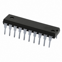
74HCT640N,652 NXP Semiconductors, 74HCT640N,652 Datasheet - Page 3

74HCT640N,652
Manufacturer Part Number
74HCT640N,652
Description
IC TRANSCEIVER 3ST 8BIT 20DIP
Manufacturer
NXP Semiconductors
Series
74HCTr
Datasheet
1.74HCT640D653.pdf
(6 pages)
Specifications of 74HCT640N,652
Logic Type
Transceiver, Inverting
Package / Case
20-DIP (0.300", 7.62mm)
Number Of Elements
1
Number Of Bits Per Element
8
Current - Output High, Low
6mA, 6mA
Voltage - Supply
4.5 V ~ 5.5 V
Operating Temperature
-40°C ~ 125°C
Mounting Type
Through Hole
Logic Family
74HCT
Number Of Channels Per Chip
8
Input Level
TTL
Output Level
CMOS
Output Type
3-State
High Level Output Current
- 6 mA
Low Level Output Current
6 mA
Propagation Delay Time
9 ns
Supply Voltage (max)
5.5 V
Supply Voltage (min)
4.5 V
Maximum Operating Temperature
+ 125 C
Function
Bus Transceiver
Input Bias Current (max)
8 uA
Maximum Power Dissipation
750 mW
Minimum Operating Temperature
- 40 C
Mounting Style
Through Hole
Polarity
Inverting
Number Of Circuits
8
Lead Free Status / RoHS Status
Lead free / RoHS Compliant
Lead Free Status / RoHS Status
Lead free / RoHS Compliant, Lead free / RoHS Compliant
Other names
568-1562-5
74HCT640N
933670960652
74HCT640N
933670960652
Philips Semiconductors
PIN DESCRIPTION
March 1988
PIN NO.
1
2, 3, 4, 5, 6, 7, 8, 9
10
18, 17, 16, 15, 14, 13, 12, 11 B
19
20
Octal bus transceiver; 3-state; inverting
Fig.1 Pin configuration.
Fig.3 IEC logic symbol.
SYMBOL NAME AND FUNCTION
DIR
A
GND
OE
V
0
0
CC
to A
to B
7
7
FUNCTION TABLE
Note
1. H = HIGH voltage level
OE
direction control
data inputs/outputs
ground (0 V)
data inputs/outputs
output enable input (active LOW)
positive supply voltage
H
L
L
L = LOW voltage level
X = don’t care
Z = high impedance OFF-state
inputs
Fig.2 Logic symbol.
DIR
H
X
L
A
A=B
inputs
Z
3
n
inputs/outputs
B
inputs
B=A
Z
n
Fig.4 Functional diagram.
74HC/HCT640
Product specification


