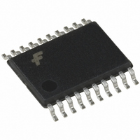
74VHCT541AMTC Fairchild Semiconductor, 74VHCT541AMTC Datasheet - Page 2

74VHCT541AMTC
Manufacturer Part Number
74VHCT541AMTC
Description
IC BUFF/DVR TRI-ST 8BIT 20TSSOP
Manufacturer
Fairchild Semiconductor
Series
74VHCTr
Datasheet
1.74VHCT541AMTCX.pdf
(7 pages)
Specifications of 74VHCT541AMTC
Logic Type
Buffer/Line Driver, Non-Inverting
Number Of Elements
1
Number Of Bits Per Element
8
Current - Output High, Low
8mA, 8mA
Voltage - Supply
4.5 V ~ 5.5 V
Operating Temperature
-40°C ~ 85°C
Mounting Type
Surface Mount
Package / Case
20-TSSOP
Package
20TSSOP
Logic Family
VHCT
Logic Function
Buffer/Line Driver
Number Of Outputs Per Chip
8
Output Type
3-State
Input Signal Type
Single-Ended
Maximum Propagation Delay Time @ Maximum Cl
7.9@5V ns
Polarity
Non-Inverting
Number Of Channels Per Chip
8
Supply Voltage (max)
5.5 V
Supply Voltage (min)
4.5 V
Maximum Operating Temperature
+ 85 C
Mounting Style
SMD/SMT
High Level Output Current
- 8 mA
Low Level Output Current
8 mA
Minimum Operating Temperature
- 40 C
Number Of Lines (input / Output)
8 / 8
Propagation Delay Time
7.9 ns at 5 V
Logical Function
Buffer/Line Driver
Number Of Elements
1
Number Of Channels
8
Number Of Inputs
8
Number Of Outputs
8
Operating Supply Voltage (typ)
5V
Package Type
TSSOP
Operating Supply Voltage (max)
5.5V
Operating Supply Voltage (min)
4.5V
Quiescent Current
4uA
Technology
CMOS
Pin Count
20
Mounting
Surface Mount
Operating Temp Range
-40C to 85C
Operating Temperature Classification
Industrial
Lead Free Status / RoHS Status
Lead free / RoHS Compliant
Available stocks
Company
Part Number
Manufacturer
Quantity
Price
Company:
Part Number:
74VHCT541AMTC
Manufacturer:
Fairchild Semiconductor
Quantity:
1 813
Company:
Part Number:
74VHCT541AMTCX
Manufacturer:
FAIRCHILD
Quantity:
500
Part Number:
74VHCT541AMTCX
Manufacturer:
ON/安森美
Quantity:
20 000
www.fairchildsemi.com
V
V
V
V
I
I
I
I
I
OZ
IN
CC
CCT
OFF
Absolute Maximum Ratings
DC Electrical Characteristics
IH
IL
Symbol
OH
OL
Supply Voltage (V
DC Input Voltage (V
DC Output Voltage (V
Input Diode Current (I
Output Diode Current (I
DC Output Current (I
DC V
Storage Temperature (T
Lead Temperature (T
(Note 3)
(Note 4)
(Note 5)
(Soldering, 10 seconds)
CC
/GND Current (I
HIGH Level Input Voltage
LOW Level Input Voltage
HIGH Level Output Voltage
LOW Level Output Voltage
3-STATE Output
Off-State Current
Input Leakage Current
Quiescent Supply Current
Maximum I
Output Leakage Current
Parameter
CC
CC
IN
)
OUT
/Input
L
)
OUT
IK
)
)
OK
CC
STG
)
)
)
)
)
4.5
4.5
0
V
4.5
4.5
(V)
4.5
4.5
5.5
5.5
5.5
0
CC
5.5
0.5V to V
5.5
5.5
65 C to 150 C
0.5V to 7.0V
0.5V to 7.0V
(Note 2)
3.94
0.5V to 7.0V
Min
2.0
4.4
CC
+ 0.5V
20 mA
20 mA
25 mA
75 mA
260 C
T
A
Typ
4.5
0.0
25
q
2
C
Recommended Operating
Conditions
Note 2: Absolute Maximum Ratings are values beyond which the device
may be damaged or have its useful life impaired. The databook specifica-
tions should be met, without exception, to ensure that the system design is
reliable over its power supply, temperature, and output/input loading vari-
ables. Fairchild does not recommend operation outside databook specifica-
tions.
Note 3: When Outputs are in OFF-State OR when V
Note 4: HIGH or LOW state I
observed.
Note 5: V
Note 6: Unused inputs must be held HIGH or LOW. They may not float.
Supply Voltage (V
Input Voltage (V
Output Voltage (V
Operating Temperature (T
Input Rise and Fall Time (t
r
(Note 4)
(Note 3)
V
Max
0.36
r
1.35
0.8
0.1
0.25
4.0
0.5
0.1
CC
OUT
5.0V 0.5V
T
GND,.V
A
3.80
Min
2.0
4.4
IN
40
OUT
)
OUT
CC
q
(Note 6)
C to
)
!
)
V
Max
0.44
r
r
40.0
1.50
CC
0.8
0.1
5.0
2.5
1.0
85
OUT
(Outputs Active).
OPR
r
q
, t
C
f
absolute maximum rating must be
)
)
Units
mA
P
P
P
P
V
V
V
V
V
V
A
A
A
A
V
V
V
V
V
V
V
Other Inputs
V
IN
IN
IN
OUT
IN
IN
IN
OUT
CC
V
V
V
5.5V or GND
V
3.4V
IH
IL
IH
CC
V
5.5V
Conditions
0V.
40 C to 85 C
4.5V to 5.5V
CC
or V
or GND
0V to 5.5V
0
I
I
I
I
or GND
OH
OH
OL
OL
0V to 5.5V
0V to V
IL
V
20 ns/V
CC
50
8 mA
50
8 mA
or GND
CC
P
P
A
A


