74HCT640DB,112 NXP Semiconductors, 74HCT640DB,112 Datasheet - Page 16
74HCT640DB,112
Manufacturer Part Number
74HCT640DB,112
Description
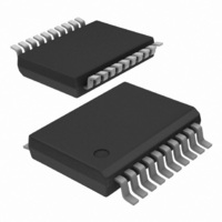
IC TRANSCEIVER 3ST 8BIT 20SSOP
Manufacturer
NXP Semiconductors
Series
74HCTr
Datasheets
1.74HCT4046ADB112.pdf
(19 pages)
2.74HCT4046ADB112.pdf
(23 pages)
3.74HCT640D653.pdf
(6 pages)
Specifications of 74HCT640DB,112
Logic Type
Transceiver, Inverting
Package / Case
20-SSOP
Number Of Elements
1
Number Of Bits Per Element
8
Current - Output High, Low
6mA, 6mA
Voltage - Supply
4.5 V ~ 5.5 V
Operating Temperature
-40°C ~ 125°C
Mounting Type
Surface Mount
Logic Family
74HCT
Number Of Channels Per Chip
8
Input Level
TTL
Output Level
TTL
Output Type
3-State
High Level Output Current
- 6 mA
Low Level Output Current
6 mA
Propagation Delay Time
9 ns
Supply Voltage (max)
5.5 V
Supply Voltage (min)
4.5 V
Maximum Operating Temperature
+ 125 C
Function
Inverting
Input Bias Current (max)
8 uA
Minimum Operating Temperature
- 40 C
Mounting Style
SMD/SMT
Polarity
Inverting
Number Of Circuits
8
Lead Free Status / RoHS Status
Lead free / RoHS Compliant
Lead Free Status / RoHS Status
Lead free / RoHS Compliant, Lead free / RoHS Compliant
Other names
568-2896-5
935190190112
935190190112


Philips Semiconductors
HCMOS family characteristics
FAMILY SPECIFICATIONS
AC CHARACTERISTICS
The “AC CHARACTERISTICS” table lists the guaranteed
limits when a device is tested under the conditions given in
the AC Test Circuits and Waveforms section.
TEST CIRCUITS
Good high-frequency wiring practices should be used in
test circuits. Capacitor leads should be as short as
possible to minimize ripples on the output waveform
transitions and undershoot. Generous ground metal
(preferably a ground-plane) should be used for the same
reasons. A V
decoupling capacitor should be provided
CC
at the test socket, also with short leads. Input signals
should have rise and fall times of 6 ns, a signal swing of
0 V to V
for 74HC and 0 V to 3 V for 74HCT; a 1.0 MHz
CC
square wave is recommended for most propagation delay
tests. The repetition rate must be increased for testing
f
. Two pulse generators are usually required for testing
max
such parameters as set-up time, hold time and removal
time. f
is also tested with 6 ns input rise and fall times,
max
with a 50% duty factor, but for typical f
as high as
max
60 MHz, there are no constraints on rise and fall times.
March 1988
16
Related parts for 74HCT640DB,112
Image
Part Number
Description
Manufacturer
Datasheet
Request
R

Part Number:
Description:
IC TRANSCEIVER 3ST 8BIT 20SOIC
Manufacturer:
NXP Semiconductors
Datasheet:
Part Number:
Description:
IC TRANSCEIVER 3ST 8BIT 20SOIC
Manufacturer:
NXP Semiconductors
Datasheet:
Part Number:
Description:
Bus Transceivers OCT 3-STATE TRANSCVR INV
Manufacturer:
NXP Semiconductors
Part Number:
Description:
NXP Semiconductors designed the LPC2420/2460 microcontroller around a 16-bit/32-bitARM7TDMI-S CPU core with real-time debug interfaces that include both JTAG andembedded trace
Manufacturer:
NXP Semiconductors
Datasheet:

Part Number:
Description:
NXP Semiconductors designed the LPC2458 microcontroller around a 16-bit/32-bitARM7TDMI-S CPU core with real-time debug interfaces that include both JTAG andembedded trace
Manufacturer:
NXP Semiconductors
Datasheet:
Part Number:
Description:
NXP Semiconductors designed the LPC2468 microcontroller around a 16-bit/32-bitARM7TDMI-S CPU core with real-time debug interfaces that include both JTAG andembedded trace
Manufacturer:
NXP Semiconductors
Datasheet:
Part Number:
Description:
NXP Semiconductors designed the LPC2470 microcontroller, powered by theARM7TDMI-S core, to be a highly integrated microcontroller for a wide range ofapplications that require advanced communications and high quality graphic displays
Manufacturer:
NXP Semiconductors
Datasheet:
Part Number:
Description:
NXP Semiconductors designed the LPC2478 microcontroller, powered by theARM7TDMI-S core, to be a highly integrated microcontroller for a wide range ofapplications that require advanced communications and high quality graphic displays
Manufacturer:
NXP Semiconductors
Datasheet:
Part Number:
Description:
The Philips Semiconductors XA (eXtended Architecture) family of 16-bit single-chip microcontrollers is powerful enough to easily handle the requirements of high performance embedded applications, yet inexpensive enough to compete in the market for hi
Manufacturer:
NXP Semiconductors
Datasheet:
Part Number:
Description:
The XA-S3 device is a member of Philips Semiconductors? XA(eXtended Architecture) family of high performance 16-bitsingle-chip microcontrollers
Manufacturer:
NXP Semiconductors
Datasheet:

Part Number:
Description:
The NXP BlueStreak LH75401/LH75411 family consists of two low-cost 16/32-bit System-on-Chip (SoC) devices
Manufacturer:
NXP Semiconductors
Datasheet:
Part Number:
Description:
The NXP LPC3130/3131 combine an 180 MHz ARM926EJ-S CPU core, high-speed USB2
Manufacturer:
NXP Semiconductors
Datasheet:
Part Number:
Description:
The NXP LPC3141 combine a 270 MHz ARM926EJ-S CPU core, High-speed USB 2
Manufacturer:
NXP Semiconductors
Part Number:
Description:
The NXP LPC3143 combine a 270 MHz ARM926EJ-S CPU core, High-speed USB 2
Manufacturer:
NXP Semiconductors