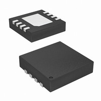
ISL45042IRZ-TK Intersil, ISL45042IRZ-TK Datasheet - Page 7

ISL45042IRZ-TK
Manufacturer Part Number
ISL45042IRZ-TK
Description
IC LCD MODULE CALIBRATOR 8-DFN
Manufacturer
Intersil
Type
Calibratorr
Datasheet
1.ISL45042IRZ.pdf
(9 pages)
Specifications of ISL45042IRZ-TK
Applications
LCD Display
Mounting Type
Surface Mount
Package / Case
8-TDFN
Lead Free Status / RoHS Status
Lead free / RoHS Compliant
Power Supply Sequence
The recommended power supply sequencing is shown in
Figure 6. When applying power, VDD should be applied
before or at the same time as AVDD. The minimum time for
t
AVDD is not important. Do not remove VDD or AVDD within
100ms of the start of the EEPROM programming cycle.
Removing power before the EEPROM programming cycle is
completed may result in corrupted data in the EEPROM.
Verifying the Programmed Value
The following sequence can be used to verify the
programmed value without having to sequence the V
supply. To verify the programmed value, follow the following
steps. The ISL45042 will read memory contents and be set
to that value when the CE pin is grounded.
VS
1. Power-up the ISL45042.
2. CE pin = V
3. Change counter value with CTL pin to desired value.
4. CTL = more than 4.9V and 200ms. Counter value
5. Change the counter value with CTL pin to a different
6. CE pin = Ground.
7. Check that the output value is the one programmed in
A
V
is 0µs. When removing power, the sequence of VDD and
programmed.
value.
Step 4.
VDD
DD
FIGURE 6. POWER SUPPLY SEQUENCE
DD.
7
t
VS
DD
ISL45042
Generating VDD and CE supply from a Larger
Voltage Source
The CE pin has an internal pull-down resistor (see
R
400kΩ to 5MΩ. If your design is using a resistor divider
network to generate the 3.3V supply (for both V
enable programming) from a larger voltage source, the
400kΩ (worst case) resistor needs to be taken into account
as a parallel resistance when the CE pin is connected to this
source. Another design concern is to be able to provide
enough supply current during programming. The ISL45042
draws about 2mA during this process. Recommended
resistor values are shown in Figure 7. This design will result
in an additional 0.83mA quiescent current flowing through
resistors R
INTERNAL
FIGURE 7. APPLICATION GENERATING VDD AND VCE
V
CC
VCE
= 5V
A
in Figure 7). The impedance of this resistor is
and R
4kΩ
VOLTAGES
R
2kΩ
R
B
A
CE
B
.
R
INTERNAL
ISL45042
= 400kΩ to 5MΩ
SCHMITT
TRIGGER
DD
CE LOGIC
and CE to
April 13, 2011
FN6072.9


