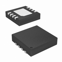
ISL45042IRZ-TK Intersil, ISL45042IRZ-TK Datasheet - Page 5

ISL45042IRZ-TK
Manufacturer Part Number
ISL45042IRZ-TK
Description
IC LCD MODULE CALIBRATOR 8-DFN
Manufacturer
Intersil
Type
Calibratorr
Datasheet
1.ISL45042IRZ.pdf
(9 pages)
Specifications of ISL45042IRZ-TK
Applications
LCD Display
Mounting Type
Surface Mount
Package / Case
8-TDFN
Lead Free Status / RoHS Status
Lead free / RoHS Compliant
Application Information
The application circuit to adjust the V
panel is shown in Figure 1. The ISL45042 has a 128-step
sink current resolution. The output is connected to an
external voltage divider that decreases the output V
voltage as you increase the ISL45042 sink current.
CTL Pin
The adjustment of the output V
programming of the non-volatile memory are provided
through a single pin called CTL when the CE pin is high.
The output V
high transition (0.8*V
voltage is decreased with a mid (V
(0.3*V
or maximum value is reached on the 128 steps, the device
will not overflow or underflow beyond that minimum or
maximum value.
Programming of the non-volatile memory occurs when the
CTL pin exceeds 4.9V. The CTL signal needs to remain
above 4.9V for more than 200µs. The level and timing
needed to program the non-volatile memory is given in
FIGURE 1. VCOM ADJUSTMENT IN AN LCD PANEL
DD
COLUMN
DRIVER
CTL
CE
) on the CTL pin (see Figure 8). Once the minimum
AVDD
SET
ISL45042
COM
R
SET
voltage is increased with a mid (V
+
-
DD
OUT
) on the CTL pin. The output V
I
SINK
5
COM
SINGLE PIXEL
IN LCD PANEL
DD
voltage and the
COM
/2) to low transition
AVDD
R
R
voltage in an LCD
1
2
VCOM
COM
DD
COM
/2) to
ISL45042
Figure 2. It then takes a maximum of 100ms for the
programming to be completed inside the device.
When the part is programmed, the counter setting is loaded
into the non-volatile memory. This value will be loaded from
the non-volatile memory during initial power-up or when the
CE pin is pulled low.
Once the programming is completed, it is recommended that
the user float the CTL pin. The CTL pin is internally tied to a
resistor network connected to ground. If left floating, the
voltage at the CTL pin will equal V
conditions, no additional pulses will be seen by the Up/Down
counter via the CTL pin. To prevent further programming,
ground the CE pin.
CTL should have a noise filter to reduce bouncing or noise
on the input that could cause unwanted counting when the
CE pin is high. The board should have an additional ESD
protection circuit, with a series 1kΩ resistor and a shunt
0.01µF capacitor connected on the CTL pin, (see Figure 3).
To avoid unintentional adjustment, the ISL45042 guarantees
to reject CTL pulses shorter than 20µs.
During Initial Power-up (only), to avoid the possibility of a
false pulse (since the internal comparators come up in an
unknown state), the very first CTL pulse is ignored. See
Figure 8 for the timing information.
CE Pin
To adjust the output voltage, the CE pin must be pulled high
(VDD). The CE pin has an internal pull-down resistor to
prevent unwanted reprogramming of the EEPROM. To
minimize current consumption, the impedance of this resistor
is high: 400kΩ to 5MΩ (see R
Transitions of the CE pin are recommended to be less than
10µs.
Replacing Existing Mechanical Potentiometer
Circuits
Figure 4 shows the common adjustment mechanical circuits
and equivalent replacement with the ISL45042.
4.9V
CTL VOLTAGE
FIGURE 2. EEPROM PROGRAMMING
CTL
>200µs
PT
INTERNAL
DD
/2. Under these
in Figure 7).
TIME
April 13, 2011
FN6072.9


