1744276-1 TE Connectivity, 1744276-1 Datasheet

1744276-1

Manufacturer Part Number
1744276-1
Description
Manufacturer
TE Connectivity
Datasheets

Specifications of 1744276-1

Termination Method To Wire/cable
Crimp
Wire Size (mm² [awg])
0.12-0.4² [26-22]
Used For
CST-100 Housings
Wire Insulation Diameter (mm [in])
0.89 – 1.65 [0.035 – 0.065]
Dual Wipe Contact
Yes
Contact Configuration
CST-100 Contacts
Contact Plating, Mating Area, Material
Pre-Tin
Contact Base Material
Phosphor Bronze
Contact Shape
Box
Rohs/elv Compliance
RoHS compliant, ELV compliant
Lead Free Solder Processes
Not relevant for lead free process
Rohs/elv Compliance History
Always was RoHS compliant
Packaging Method
Strip
Packaging Quantity
5,500
1.
1.1.
1.2.
1.3.
2.
2.1.
2.2.
3.
3.1.
3.2.
©2011 Tyco Electronics Corporation,
a TE Connectivity Ltd. Company
All Rights Reserved
TE logo is a trademark.
SCOPE
Content
This specification covers performance, tests and quality requirements for the TE Connectivity (TE)
.100 inch centerline Crimp-Snap connectors. The Crimp-Snap Terminal .100 product is a wire-to-board
connection consisting of crimp-snap contacts seated in a housing that mates to .025 inch square post
headers on .100 inch centerline and is designed to be terminated to 22 to 26 AWG wire.
Qualification
When tests are performed on the subject product line, procedures specified in Figure 1 shall be used.
All inspections shall be performed using the applicable inspection plan and product drawing.
Successful qualification testing on the subject product line was completed on 18Apr96. The
Qualification Test Report number for this testing is 501-341. Additional testing was completed on
10Jul09 and 27Jul10. This documentation is on file at and available from Engineering Practices and
Standards (EPS).
APPLICABLE DOCUMENTS
The following documents form a part of this specification to the extent specified herein. Unless
otherwise specified, the latest edition of the document applies. In the event of conflict between the
requirements of this specification and the product drawing, the product drawing shall take precedence.
In the event of conflict between requirements of this specification and the referenced documents, this
specification shall take precedence.
TE Documents
!
!
!
!
!
Industry Standard
EIA-364: Electrical Connector/Socket Test Procedures Including Environmental Classifications
REQUIREMENTS
Design and Construction
Product shall be of the design, construction and physical dimensions specified on the applicable product
drawing.
Materials
Materials used in the construction of this product shall be as specified on the applicable product
drawing.
109-1: Test Specification (General Requirements for Test Specifications)
109 Series: Test Specifications as indicated in Figure 1
109-151: Test Specification (Current Rating Verification)
114-16019: Application Specification (CST-100 Connectors for Crimp Snap Terminals)
501-341: Qualification Test Report (.100 Inch Centerline Crimp-Snap Connectors)
| Indicates change
*Trademark
Product
Specification
.100 Inch Centerline Crimp-Snap Connectors
For latest revision, visit our website at www.te.com/documents.
For Regional Customer Service, visit our website at www.te.com
Other products, logos, and company names might be trademarks of their respective owners.
108-1328
11Mar11 Rev C
1 of 8
LOC B

Related parts for 1744276-1

1744276-1 Summary of contents

Page 1

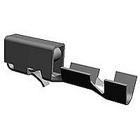
... SCOPE 1.1. Content This specification covers performance, tests and quality requirements for the TE Connectivity (TE) .100 inch centerline Crimp-Snap connectors. The Crimp-Snap Terminal .100 product is a wire-to-board connection consisting of crimp-snap contacts seated in a housing that mates to .025 inch square post headers on .100 inch centerline and is designed to be terminated AWG wire. ...

Page 2

Ratings ! Voltage: 250 volts AC ! Current: See Figure 4 for applicable current carrying capability ! Temperature: -55 to 105° C 3.4. Performance and Test Description Product is designed to meet the electrical, mechanical and environmental performance requirements ...

Page 3

Test Description Physical shock. Durability. Mating force. Unmating force. Crimp tensile. Thermal shock. Humidity/temperature cycling. Temperature life. Mixed flowing gas. Shall meet visual requirements, show no physical damage and shall meet requirements of NOTE additional tests as specified in Test ...

Page 4

Product Qualification and Requalification Test Sequence Test or Examination Examination of product Termination resistance Insulation resistance Dielectric withstanding voltage Temperature rise vs current Solderability Sinusoidal vibration Physical shock Durability Mating force Unmating force Crimp tensile Thermal shock Humidity/temperature cycling ...

Page 5

QUALITY ASSURANCE PROVISIONS 4.1. Qualification Testing A. Specimen Selection Specimens shall be prepared in accordance with applicable Instruction Sheets and shall be selected at random from current production. Test groups and 4 shall each consist of ...

Page 6

Rev C Figure 3 Termination Resistance Measurement Points 108-1328 ...

Page 7

Percent Connector Loading (20 position connector) To determine the acceptable current carrying capacity for the percentage connector NOTE loading and wire gage indicated, use the Multiplication Factor (F) from the above chart and multiply it times the Base rated Current ...

Page 8

Rev C Figure 5 Vibration & Physical Shock Mounting Fixture 108-1328 ...

Related keywords