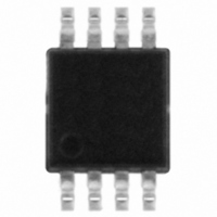
LM293ST STMicroelectronics, LM293ST Datasheet - Page 4

LM293ST
Manufacturer Part Number
LM293ST
Description
IC COMP DUAL LP BIPO MINI 8SOIC
Manufacturer
STMicroelectronics
Type
General Purposer
Datasheet
1.LM393PT.pdf
(16 pages)
Specifications of LM293ST
Number Of Elements
2
Output Type
CMOS, DTL, ECL, MOS, Open-Collector, TTL
Voltage - Supply
2 V ~ 36 V, ±1 V ~ 18 V
Mounting Type
Surface Mount
Package / Case
8-TSSOP, 8-MSOP (0.118", 3.00mm Width)
Number Of Channels
2 Channels
Response Time
1.3 us
Offset Voltage (max)
5 mV
Input Bias Current (max)
250 nA
Supply Voltage (max)
36 V
Supply Voltage (min)
2 V
Supply Current (max)
1 mA
Maximum Power Dissipation
580 mW
Maximum Operating Temperature
+ 105 C
Mounting Style
SMD/SMT
Minimum Operating Temperature
- 40 C
Number Of Elements
2
Technology
Bipolar
Input Offset Voltage
5mV
Input Bias Current (typ)
250nA
Single Supply Voltage (typ)
3/5/9/12/15/18/24/28V
Dual Supply Voltage (typ)
±3/±5/±9/±12/±15V
Power Supply Requirement
Single/Dual
Voltage Gain In Db
106.02dB
Single Supply Voltage (min)
2V
Single Supply Voltage (max)
36V
Dual Supply Voltage (min)
±1V
Dual Supply Voltage (max)
±18V
Power Dissipation
580mW
Operating Temp Range
-40C to 105C
Operating Temperature Classification
Industrial
Mounting
Surface Mount
Pin Count
8
Package Type
MSOP
Lead Free Status / RoHS Status
Lead free / RoHS Compliant
Other names
497-4265-2
Available stocks
Company
Part Number
Manufacturer
Quantity
Price
Company:
Part Number:
LM293ST
Manufacturer:
STMicroelectronics
Quantity:
60 237
Company:
Part Number:
LM293ST
Manufacturer:
SOSHIN
Quantity:
4 343
Part Number:
LM293ST
Manufacturer:
ST
Quantity:
20 000
Electrical characteristics
3
Table 3.
1. At output switch point, V
2. The direction of the input current is out of the IC due to the PNP input stage. This current is essentially constant,
3. The response time specified is for a 100 mV input step with 5 mV overdrive. For larger overdrive signals 300 ns can be
4. Positive excursions of input voltage may exceed the power supply level. As long as the other voltage remains within the
4/16
Symbol
V
I
A
I
I
V
V
t
V
independent of the state of the output, so no loading charge exists on the reference of input lines.
obtained.
common-mode range, the comparator will provide a proper output state. The low input voltage state must not be less than
-0.3 V (or 0.3 V below the negative power supply, if used).
sink
OH
t
I
I
CC
rel
io
ib
OL
re
vd
CC
io
id
+
-1.5 V).
Input offset voltage
Input offset current
Input bias current (I
Large signal voltage gain
V
Supply current (all comparators)
Differential input voltage
Low level output voltage
V
High level output current
V
Output sink current V
Response time
R
Large signal response time
R
V
CC
id
CC
(ref)
L
L
T
T
T
V
V
T
T
= 5.1kΩ connected to V
= 5.1kΩ connected to V
V
min
min
min
= -1V, I
min
min
Electrical characteristics
CC
CC
CC
= 15V, R
= V
= +1.4v
= +5V, no load
= +30V, no load
≤ T
≤ T
≤ T
≤ T
≤ T
+
o
= +5V, V
= 30V, V
amb
amb
amb
amb
amb
sink
L
= 4mA
o
≤ T
≤ T
≤ T
= 15kΩ, V
≤ T
≤ T
(4)
≈ 1.4 V, R
Parameter
max
max
max
max
id
max
CC
+
(1)
= 1V
or I
id
-
= 0V, T
= 1V, V
-
(3)
)
o
s
CC
CC
(2)
= 1V to 11V
= 0 with V
+
+
o
, e
amb
= 1.5V
l
= TTL,
= +25°C (unless otherwise specified)
CC
Doc ID 2164 Rev 11
+
from 5 V to 30 V, and over the full common-mode range (0 V to
Min.
50
6
LM193A - LM293A
Typ.
200
250
300
LM393A
0.4
0.1
1.3
25
16
1
3
1
Max.
V
100
100
300
400
700
2.5
25
CC
2
4
1
1
+
Min
50
6
LM193- LM293
LM193, LM293, LM393
Typ.
200
250
300
0.4
0.1
1.3
LM393
25
16
1
5
1
V
Max.
150
250
400
400
700
2.5
50
CC
5
9
1
1
+
V/mV
Unit
mV
mA
mV
mA
nA
nA
nA
μA
ns
μs


