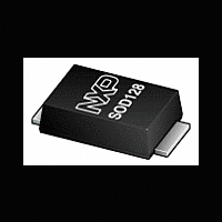
PMEG4020ETP NXP Semiconductors, PMEG4020ETP Datasheet - Page 7

PMEG4020ETP
Manufacturer Part Number
PMEG4020ETP
Description
Planar Maximum Efficiency General Application (MEGA) Schottky barrier rectifier with an integrated guard ring for stress protection, encapsulated in a SOD128 small and flat lead Surface-Mounted Device (SMD) plastic package
Manufacturer
NXP Semiconductors
Datasheet
1.PMEG4020ETP.pdf
(14 pages)
NXP Semiconductors
PMEG4020ETP
Product data sheet
Fig 8.
Fig 10. Average forward current as a function of
P
I
F(AV)
R(AV)
(W)
(A)
3.5
3.0
2.5
2.0
1.5
1.0
0.5
0.0
3
2
1
0
function of reverse voltage; typical values
ambient temperature; typical values
T
(1) δ = 1.0
(2) δ = 0.9
(3) δ = 0.8
(4) δ = 0.5
Average reverse power dissipation as a
FR4 PCB, mounting pad for cathode 1 cm
T
(1) δ = 1.0
(2) δ = 0.9
(3) δ = 0.8
(4) δ = 0.5
0
0
j
j
= 150 °C
= 175 °C
10
50
(1)
(2)
(3)
(4)
100
20
(1)
(2)
(3)
150
30
T
All information provided in this document is subject to legal disclaimers.
amb
006aac728
V
006aac730
R
(V)
(°C)
(4)
200
40
Rev. 1 — 5 October 2011
2
Fig 9.
Fig 11. Average forward current as a function of
I
I
40 V, 2 A low VF MEGA Schottky barrier rectifier
F(AV)
F(AV)
(A)
(A)
3
2
1
0
3
2
1
0
ambient temperature; typical values
ambient temperature; typical values
FR4 PCB, standard footprint
T
(1) δ = 1.0 (DC)
(2) δ = 0.5; f = 20 kHz
(3) δ = 0.2; f = 20 kHz
(4) δ = 0.1; f = 20 kHz
Average forward current as a function of
Ceramic PCB, Al
T
(1) δ = 1.0 (DC)
(2) δ = 0.5; f = 20 kHz
(3) δ = 0.2; f = 20 kHz
(4) δ = 0.1; f = 20 kHz
0
0
j
j
= 175 °C
= 175 °C
50
50
(1)
(2)
(3)
(4)
(1)
(2)
(3)
(4)
PMEG4020ETP
2
O
100
100
3
, standard footprint
150
150
© NXP B.V. 2011. All rights reserved.
T
T
amb
amb
006aac729
006aac731
(°C)
(°C)
200
200
7 of 14


