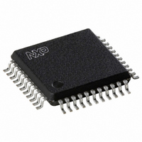
TDA9874AH/V2,557 NXP Semiconductors, TDA9874AH/V2,557 Datasheet - Page 38

TDA9874AH/V2,557
Manufacturer Part Number
TDA9874AH/V2,557
Description
IC SOUND DEMOD/DECODE 44PQFP
Manufacturer
NXP Semiconductors
Type
Demodulatorr
Datasheet
1.TDA9874AHV2557.pdf
(68 pages)
Specifications of TDA9874AH/V2,557
Applications
TV
Mounting Type
Surface Mount
Package / Case
44-QFP
Lead Free Status / RoHS Status
Lead free / RoHS Compliant
Other names
935263704557
TDA9874AHB
TDA9874AHB
TDA9874AHB
TDA9874AHB
Available stocks
Company
Part Number
Manufacturer
Quantity
Price
Company:
Part Number:
TDA9874AH/V2,557
Manufacturer:
NXP Semiconductors
Quantity:
10 000
Philips Semiconductors
Table 57 System clock frequency select
7.3.20
This register is used to define both the signal source to be
output at the I
for signal selection.
The two combinations of FM and NICAM shown in
Table 60 apply to the (rare) condition that three different
languages are being broadcast in an FM + NICAM system.
Table 58 I
Table 59 Description of the I
Table 60 Mode of the digital matrix for signal selection (bit TVSMIIS = 0)
2000 Aug 04
Digital TV sound demodulator/decoder
TVSMIIS
SYSCL1
ICSM2
BIT
0
0
1
1
7
7
6
5
4
3
2
1
0
0
0
0
0
1
I
2
S-
2
S-bus output select register (subaddress 22)
BUS
2
S-bus port and the mode of the digital matrix
O
SYMBOL
TVSMIIS
SYSCL0
ICSM2
ICSM2
ICSM1
ICSM0
ICSM1
UTPUT
ISS1
ISS0
0
1
0
1
6
0
0
1
1
0
S
ELECT
2
S-bus output select register bits
Auto-select function: for TV applications, only in combination with bit IDSWFM = 1. If
this bit is set to logic 1 it switches the matrix automatically, depending on the bits IDSTE
and IDDUA for FM and the bits S/MB, D/SB for NICAM in transmitters
subaddresses 0 and 1 (see Sections 7.4.1 and 7.4.2).
Output channel selection mode: these bits select the output channel selection mode;
see Table 60.
these bits are not used and should be set to logic 0
Signal source: these bits select the signal source; see Table 60.
R
ICSM1
ICSM0
EGISTER
5
0
1
0
1
0
SYSCLK OUTPUT
(I
2
SOSR)
L input
------------------------------------------ -
ICSM0
L OUTPUT
256f
384f
512f
768f
R input
R input
L input
L input
4
+
s
s
s
s
2
R input
38
They allow for a two-out-of-three selection for special
applications. It should be noted that the controlling
microprocessor has to assure that the FM dematrix is set
to the mono position or bit IDSWFM is set to logic 1. If the
I
influenced by the automatic FM dematrix switching
(see subaddress 11).
The default setting after Power-on reset is 0000 0000.
2
S-bus signal source is set to FM left or FM right it is
L input
------------------------------------------ -
3
0
DESCRIPTION
R OUTPUT
R input
R input
L input
L input
+
2
R input
2
0
not allowed during use of high
deviation mode
FREQUENCY
12.288
16.384
24.576
(MHz)
8.192
ISS1
1
REMARK
Product specification
TDA9874A
ISS0
0


